Pipe end groove forming machine

A forming machine and beveling technology, which is applied in the details of milling machine equipment, metal processing equipment, milling machine equipment, etc., can solve the problems of stainless steel pipe beveling, high cost, and high labor intensity, so as to ensure the welding quality of steel pipes and reduce The effect of equipment cost and improvement of construction efficiency

Active Publication Date: 2011-09-14
中国电子系统工程第四建设有限公司
View PDF5 Cites 15 Cited by
  • Summary
  • Abstract
  • Description
  • Claims
  • Application Information

AI Technical Summary

Problems solved by technology

[0003] In the existing pipeline construction, steel pipes are often cut off for installation of pipe fittings or pipe butt joints. Generally, steel pipe beveling machines are used on site, angle grinders or gas welding are used to form bevels on the ends of steel pipes, and electric beveling machines are also used in some cases; However, beveling with an angle grinder is labor-intensive and low in efficiency; gas welding is only suitable for carbon steel pipes, and stainless steel pipes cannot be beveled; while electric beveling machines are costly and the equipment is limited by specifications. Less commonly used on site
[0004] There is also a plastic pipe used in pipeline construction. The butt joint of plastic pipes is generally connected by bonding. According to the requirements of relevant specifications, in order to ensure the quality of bonding, the end of the bonded plastic pipe must also be grooved. The current The method of on-site bevel forming is to use an angle grinder to grind the shape. On the one hand, the efficiency is low, and on the other hand, the quality of the bevel forming is poor; It is inconvenient to form grooves on large diameter plastic pipes

Method used


Image

  • Pipe end groove forming machine
  • Pipe end groove forming machine
  • Pipe end groove forming machine

Examples


Embodiment Construction

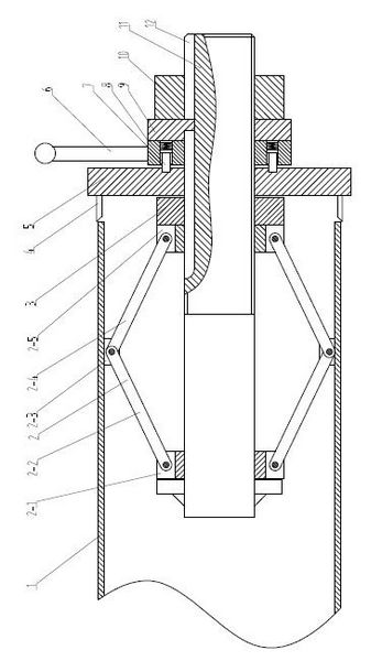
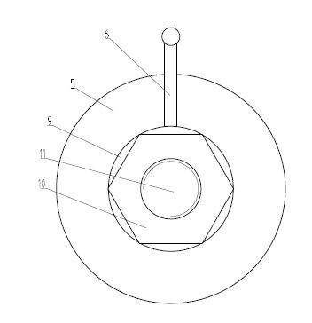
[0017] Such as figure 1 and figure 2 A pipe end bevel forming machine shown includes a central shaft 11, a fixing device fixed at one end of the central shaft 11, and a bevel forming device fixed at the middle of the central shaft 11; the fixing device is at least two with the same structure and a slider crank mechanism evenly distributed on the circumference of the central axis 11;

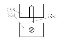
[0018] The slider crank mechanism includes a crank 2-2, a connecting rod 2-4, a fixed sleeve 2-1, a sliding sleeve 2-5 and a positioning nut 3; the fixed sleeve 2-1 is located at the left end of the central shaft 11; the One end of the crank 2-2 is hinged to the lug on the fixed sleeve 2-1, and the other end is hinged to the connecting rod 2-4; the other end of the connecting rod 2-4 is hinged to the lug on the circumference of the sliding sleeve 2-5 ; Sliding fit between the sliding sleeve 2-5 and the central shaft 11; the positioning nut 3 is in contact with the right side of the sliding sle...


PUM


Abstract

The invention discloses a pipe end groove forming machine, which comprises a central shaft, a fixed device fixedly arranged at one end of the central shaft and a groove forming device which is fixed in the middle of the central shaft, wherein the fixed device is provided with at least two crank sliding block mechanisms which have the same structure and are symmetrically arranged on the circumference of the central shaft. The groove forming machine has the advantages that: the central shaft can be positioned on a steel pipe to be machined or the inner wall of a plastic pipe by two crank connecting rod mechanisms symmetrically arranged at one end of the central shaft, at least two forming cutters are arranged on the left side face of a cutter disk, the positions of the forming cutters are adjusted according to the apertures of the steel pipe to be machined or the plastic pipe, and a driving disk is manually rotated to drive the cutter disk to rotate, so that a groove at one end of the steel pipe or the plastic pipe can be formed. The device has a simple structure, is not required to be provided with an externally-connected power device, and can finish forming the groove at one end of the steel pipe or the plastic pipe only by manual operation, ensure the welding quality of the steel pipe and the adhesive bonding quality of the plastic pipe and improve construction efficiency and reduce equipment cost.

Description

technical field [0001] The invention relates to an auxiliary equipment used in steel pipe welding or plastic pipe bonding construction, in particular to a pipe end groove forming machine. Background technique [0002] The current steel pipe welding specification requires that in order to avoid welding defects affecting the construction quality of the pipeline when the steel pipes are butt jointed, the welded ends of the steel pipes must be beveled, that is, chamfered at the welded ends; [0003] In the existing pipeline construction, steel pipes are often cut off for installation of pipe fittings or pipe butt joints. Generally, steel pipe beveling machines are used on site, angle grinders or gas welding are used to form bevels on the ends of steel pipes, and electric beveling machines are also used in some cases; However, beveling with an angle grinder is labor-intensive and low in efficiency; gas welding is only suitable for carbon steel pipes, and stainless steel pipes can...

Claims


Application Information

Patent Timeline
Patent Type & Authority Applications(China)
IPC IPC(8): B23C3/12
Inventor 侯初王世成范双怀李劲飞王鹏韩波
Owner 中国电子系统工程第四建设有限公司
Why Eureka
Try Eureka