Cooling system of automobile engine and control method thereof

An automobile engine and cooling system technology, which is applied in the direction of engine cooling, coolant flow control, engine components, etc., can solve the problems of ineffective cooling, difficult mass production, difficult processing and production, etc., and achieves easy damage and deformation. and processing and production difficulties, low cost, and the effect of improving fuel economy

Active Publication Date: 2011-09-14
CHERY AUTOMOBILE CO LTD
View PDF6 Cites 20 Cited by
  • Summary
  • Abstract
  • Description
  • Claims
  • Application Information

AI Technical Summary

Problems solved by technology

Although this cycle control method realizes the different temperature requirements of the cylinder body and the cylinder head, this completely independent structure of the cylinder body and the cylinder head is easy to cause damage to the cylinder body and the cylinder at the joint surface of the cylinder body and the cylinder head. or cylinder bore deformation
Because the junction of the cylinder block and the cylinder head is the high-temperature and high-pressure area of ​​engine combustion, however, this completely independently cooled cylinder block and cylinder head structure is sealed in this high-temperature and high-pressure area, and cannot be effectively cooled
This kind of completely independent cooling structure, in order to prevent the cylinder block from pulling or deforming, the design of the joint surface between the cylinder block and the cylinder head is often very complicated, and it is difficult to process and produce, and it is not easy to realize mass production

Method used


Image

  • Cooling system of automobile engine and control method thereof
  • Cooling system of automobile engine and control method thereof
  • Cooling system of automobile engine and control method thereof

Examples


Embodiment Construction

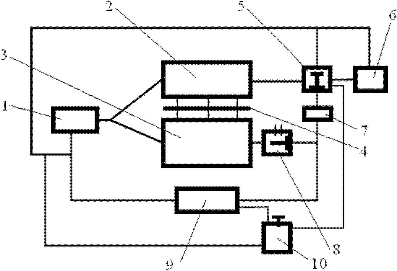
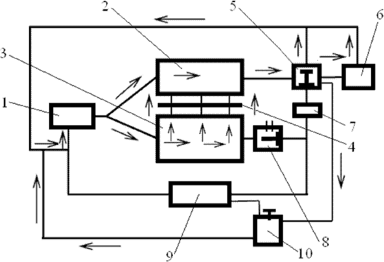
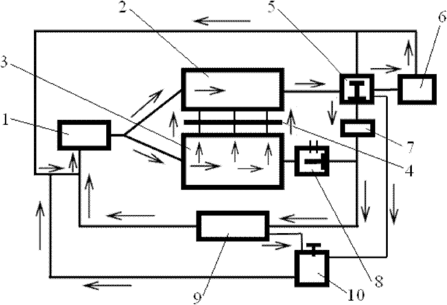
[0027] Referring to the accompanying drawings, through the description of the embodiments, the specific implementation of the present invention, such as the shape, structure, mutual position and connection relationship between the various parts, the function and working principle of each part, and the manufacturing process And the method of operation and use, etc., are described in further detail to help those skilled in the art have a more complete, accurate and in-depth understanding of the inventive concept and technical solutions of the present invention.

[0028] Such as Figure 1 to Figure 4 According to the structure of the present invention, the present invention is an automobile engine cooling system. The automobile engine includes a cylinder block 3 and a cylinder head 2 , and the cooling system is provided with a cooling water pump 1 .

[0029] In order to solve the problems existing in the current known technology described in the background technology part of this...


PUM


Abstract

The invention discloses a cooling system of an automobile engine. The automobile engine comprises a cylinder body and a cylinder cover; the cooling system is provided with a cooling water pump; the cooling water pump is respectively connected with water inlets of cooling channels of the cylinder body and the cylinder cover through cooling water pipelines; a pipeline of a water outlet of the cooling channel of the cylinder cover is provided with a common dual-valve temperature regulator; a pipeline of a water outlet of the cooling channel of the cylinder body is provided with an electronic temperature regulator; the starting temperature of the common dual-valve temperature regulator is lower than that of the electronic temperature regulator, and the starting is controlled by the actual temperature of an engine cooling liquid. By adopting the technical scheme, the cycle control of the cooling for the cylinder cover and the cylinder body of the engine respectively is realized, the technical scheme is good for improving the fuel economy and reducing emission; and the requirement of different temperatures by the cylinder cover and the cylinder body of the engine is satisfied; the problems that the cylinder body and the cylinder cover which are cooled independently and completely are easy to be damaged and deformed and the manufacturing and production are difficult are solved; and the structure of the combining surface of the cylinder body and the cylinder cover is simple, the manufacture is easy, and the cost is low.

Description

technical field [0001] The invention belongs to the technical field of automobile structure and relates to automobile engine technology, more specifically, the invention relates to an automobile engine cooling system. The invention also relates to a control method of the cooling system. Background technique [0002] At present, more than one thermostat is used in the cooling system of the automobile engine to control the circulation of the engine coolant. This engine cooling system can only cool the engine parts at the same time, and it is difficult to realize the different temperature requirements of different parts of the engine. [0003] For example: in order to improve the gas charging efficiency of the engine, the engine cylinder head hopes to be well cooled, so that the temperature of the cylinder head body is as low as possible. In order to improve the combustion performance and improve the utilization rate of the engine heat load, the engine block hopes to have a r...

Claims


Application Information

Patent Timeline
Patent Type & Authority Applications(China)
IPC IPC(8): F01P3/02F01P3/20F01P7/16
Inventor 李宏坤
Owner CHERY AUTOMOBILE CO LTD
Why Eureka
Try Eureka