High revolving speed fuel oil magnetic valve and method for measuring closing and starting points thereof

A solenoid valve and high-speed technology, applied in the field of solenoid valves, can solve the problems of poor dynamic performance, low robustness, and inconvenience of mass production of solenoid valves, and achieve reduced secondary fuel injection, precise fuel control, and low operating noise Effect

Inactive Publication Date: 2011-09-14
NANJING UNIV OF AERONAUTICS & ASTRONAUTICS
View PDF8 Cites 7 Cited by
  • Summary
  • Abstract
  • Description
  • Claims
  • Application Information

AI Technical Summary

Problems solved by technology

[0004] The closed-loop control of the solenoid valve requires real-time measurement of signals such as armature displacement, electromagnetic coil operating current, and magnetic flux. Considering factors such as installation space and production costs, such sensors are often not installed in mass-produced fuel injection systems. Therefore, Although the research on closed-loop control has made great breakthroughs in recent years and achieved an ideal landing state in the laboratory environment, it is not convenient for mass production
In recent years, some researchers have begun to study sensorless control methods. The main idea of ​​this method is to reconstruct displacement, current and magnetic flux signals based on signals that are easy to measure (usually current signals), and use the reconstructed signals for closed-loop control. , but the robustness of this method is low, and it is still in the preliminary research stage
[0005] The switching time of loading voltage and holding voltage in the traditional open-loop control method cannot change with the change of engine operating conditions, so the dynamic performance of the solenoid valve is poor

Method used


Image

  • High revolving speed fuel oil magnetic valve and method for measuring closing and starting points thereof
  • High revolving speed fuel oil magnetic valve and method for measuring closing and starting points thereof
  • High revolving speed fuel oil magnetic valve and method for measuring closing and starting points thereof

Examples


Embodiment Construction

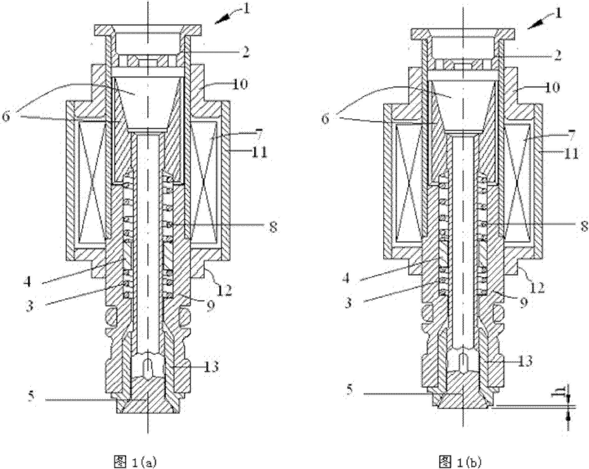
[0024] The accompanying drawings disclose non-restrictive structural schematic diagrams of preferred embodiments involved in the present invention, and the technical solutions of the present invention will be described in detail below in conjunction with the accompanying drawings.

[0025] Such as figure 1As shown, the high-speed fuel solenoid valve 1 of the present invention includes a valve body, and the two ends of the valve body are respectively equipped with a valve end cover 2 and a valve seat 13, and the valve end cover 2 is provided with an oil inlet, and the valve seat 13 Then open the oil outlet, the inner cavity of the valve body is equipped with a valve core 6, the valve core 6 is the armature, and the valve core 6 is arranged close to the valve end cover 2, and the inner cavity of the valve seat 13 is matched with the valve closing member. 5. In addition, an electromagnetic coil 7 is installed in the inner cavity of the valve, and the valve core 6 is supported on...


PUM


Abstract

The invention discloses a high revolving speed fuel oil magnetic valve and a method for measuring closing and starting points thereof. The high revolving speed fuel oil magnetic valve comprises a valve body, wherein two ends of the valve body are respectively provided with a valve end cover and a valve seat; the inner cavity of the valve body is provided with a valve core which is arranged close to the valve end cover; a valve close piece is matched in the inner cavity of the valve seat; the inner cavity of the valve body is provided with a magnetic coil; the valve core is supported on a bulge arranged in the inner cavity of the valve body through a secondary oscillating unit; the secondary oscillating unit comprises a moving block, and an upper spring and a lower spring which are respectively connected with two ends of the moving block; and the lower spring is installed on the bulge in the inner cavity of the valve body, and the upper spring is connected with the valve core. According to the invention, the amplitude value of the original system rebound vibration is reduced effectively; and through the accurate estimation of the closing and starting points of the magnetic valve, the exchanging time of the loading voltage and the retaining voltage can be determined accurately, the response speed of the magnetic valve is improved, and simultaneously the settling speed of the magnetic valve is reduced.

Description

technical field [0001] The invention relates to a solenoid valve used in an internal combustion engine fuel injection system and a method for measuring the closing start point of the solenoid valve. Through the method for measuring the closing start point of the solenoid valve, precise control of the fuel injection quantity at high speeds can be realized. Background technique [0002] The solenoid valve is one of the core components of the electronically controlled fuel injection system. The main problem in the practical application of the high-speed solenoid valve is that the collision between the solenoid core and the armature will reduce the service life of the solenoid valve and generate a lot of noise. To reduce the working noise of the solenoid valve is to reduce the seating speed of the solenoid valve, but reducing the seating speed of the solenoid valve will increase the transition time of the solenoid valve from fully open to fully closed (or fully closed to fully op...

Claims


Application Information

Patent Timeline
Patent Type & Authority Applications(China)
IPC IPC(8): F02M51/00F02M61/16F02M65/00
Inventor 张延召毛建国沈峘武超陆广敏张艳浩
Owner NANJING UNIV OF AERONAUTICS & ASTRONAUTICS
Why Eureka
Try Eureka