Infrared temperature measurement detection method for detecting solder joint reliability of circuit board

A technology of infrared temperature measurement and detection method, which is applied in the direction of material defect testing, etc., can solve the problem that solder joints cannot be detected, and achieve the effect of simple method and intuitive diagnosis

Active Publication Date: 2011-09-14
HARBIN INST OF TECH
View PDF3 Cites 30 Cited by
  • Summary
  • Abstract
  • Description
  • Claims
  • Application Information

AI Technical Summary

Problems solved by technology

[0006] The purpose of the present invention is to solve the problem that existing methods cannot detect solder joints with normal appearance and defects, and provide an infrared temperature measurement method for detecting the reliability of solder joints on circuit boards

Method used


Image

  • Infrared temperature measurement detection method for detecting solder joint reliability of circuit board
  • Infrared temperature measurement detection method for detecting solder joint reliability of circuit board
  • Infrared temperature measurement detection method for detecting solder joint reliability of circuit board

Examples


specific Embodiment approach 1

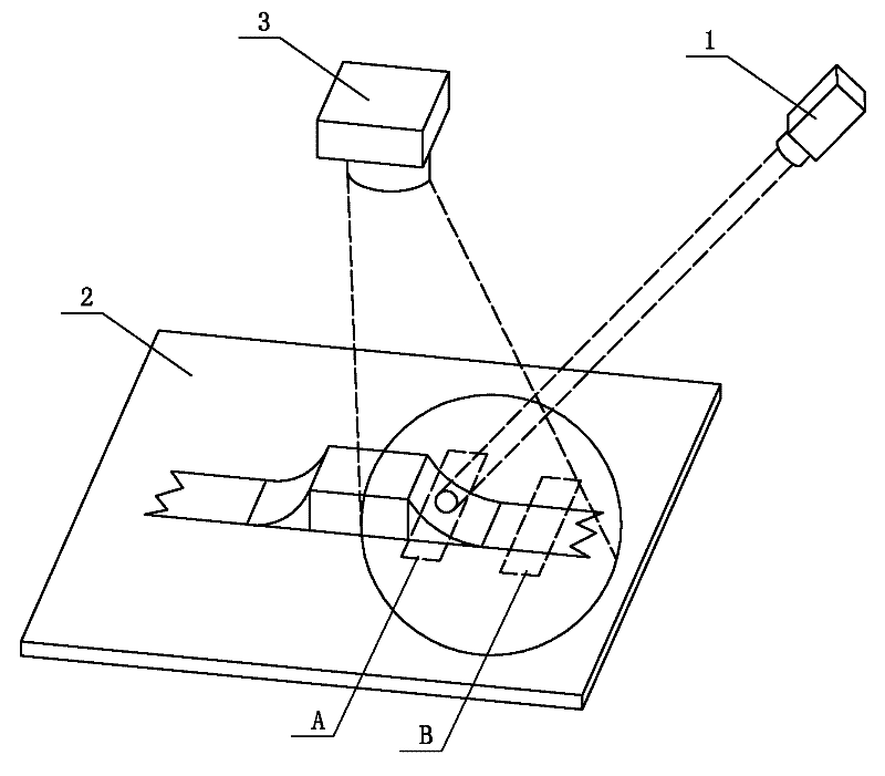
[0019] Specific implementation mode one: the following combination Figure 1 to Figure 4 To describe this embodiment,

Embodiment approach

[0020] This implementation mode includes the following steps:

[0021] Step 1: Use the infrared laser 1 to emit a beam of infrared laser light to focus on the solder joint to be detected on the circuit board 2, the duration t is: 1s≥t≥0.1s, and use the infrared thermal imager 3 to obtain the solder joint to be detected The dynamic image of the dynamic image and the dynamic image at the lead position of the solder joint to be detected, obtain the temperature distribution curve of the solder joint to be detected and the temperature distribution curve at the lead position of the solder joint to be detected;

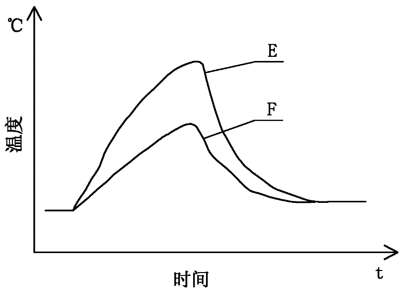
[0022] Step 2: superimposing the temperature distribution curve of the solder joint to be detected and the temperature distribution curve at the lead wire of the solder joint to be detected;

[0023] Step 3: Judging the superposition result of Step 2:

[0024] When the distribution trends of the two temperature distribution curves are the same, and the highest temperature p...

specific Embodiment approach 2

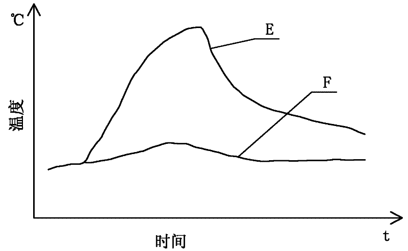
[0032] Specific implementation mode two: the following combination image 3 and Figure 4 Describe this embodiment, this embodiment is a further description of Embodiment 1, the specific determination method of the unqualified solder joint in the step 3 is:

[0033] When the distribution trends of the two temperature distribution curves are the same, and the temperature distribution curve at the lead wire of the solder joint to be detected approaches a straight line, it is determined that the solder joint to be detected is a completely open circuit;

[0034] When the trends of the two temperature distribution curves are different, there is a phase difference between the highest temperature points on the two temperature distribution curves, and the highest temperature point on the temperature distribution curve at the lead wire of the solder joint to be detected lags behind the temperature distribution curve of the solder joint to be detected At the highest temperature point a...


PUM

PropertyMeasurementUnit
poweraaaaaaaaaa

Abstract

The invention discloses an infrared temperature measurement detection method for detecting solder joint reliability of a circuit board, which belongs to the technical field of faulty soldering detection of solder joints and solves the problem that the prior method cannot detect the faulty solder point of which the appearance is normal. The infrared temperature measurement detection method comprises the following steps of: 1, concentrating an infrared laser beam emitted by an infrared laser device on a solder joint to be detected of the circuit board, using a thermal infrared imager to obtain a dynamic image of the solder joint to be detected and a dynamic image of a lead wire part of the solder joint to be detected, and getting temperature distribution curves of the solder joint to be detected and the lead wire part of the solder joint to be detected; 2, overlaying the temperature distribution curve of the solder joint with that of the lead wire part of the solder joint to be detected according to same proportion; 3, judging the overlaying result: when the two temperature distribution curves have same distribution trend, and the highest temperature points on the two temperature distribution curves are synchronous, judging that the solder joint to be detected is a qualified solder joint; otherwise, judging that the solder joint to be detected is unqualified. The infrared temperature measurement detection method is suitable for detecting the solder joint reliability of the circuit board.

Description

technical field [0001] The invention relates to an infrared temperature measurement detection method for detecting the reliability of solder joints of circuit boards, and belongs to the technical field of solder joint virtual solder detection of printed circuit boards. Background technique [0002] Welding of solder joints is a common problem in the production process of printed circuit boards (PCB). Due to the complexity of the factors causing solder joints, it is impossible to completely remove them in the production process. Therefore, the detection of solder joints is very important. important. At present, the detection methods of virtual solder joints mainly include automatic optical inspection (AOI) method and automatic X-ray inspection (AXI) method. [0003] The automatic optical inspection (AOI) method captures the mounting image on the surface of the circuit board component by the CCD camera, and then performs image processing through software, and compares the par...

Claims


Application Information

Patent Timeline
Patent Type & Authority Applications(China)
IPC IPC(8): G01N25/72
Inventor 孔令超田艳红王春青杭春进刘威
Owner HARBIN INST OF TECH
Why Eureka
Try Eureka