Eureka AIR delivers breakthrough ideas for toughest innovation challenges, trusted by R&D personnel around the world.

High-speed and high-precision all-fiber polarization control device

A polarization control, high-precision technology, applied in the direction of optics, optical components, instruments, etc., can solve problems such as complex control circuits, high bias voltage, complex structure, etc., to avoid mechanical movement, precise and rapid control, and low cost Effect

Inactive Publication Date: 2011-09-14
BEIJING UNIV OF POSTS & TELECOMM
View PDF1 Cites 9 Cited by
  • Summary
  • Abstract
  • Description
  • Claims
  • Application Information

AI Technical Summary

Problems solved by technology

The mechanism is to use the electro-optical effect of the crystal to introduce birefringence in different directions and then control the polarization state. This method has high precision and fast speed, but it requires complex control circuits and high bias voltage, and the structure is more complicated and the cost is higher.

Method used


Image

  • High-speed and high-precision all-fiber polarization control device
  • High-speed and high-precision all-fiber polarization control device
  • High-speed and high-precision all-fiber polarization control device

Examples


Embodiment Construction

[0026] Below in conjunction with accompanying drawing and specific embodiment the present invention is described in further detail:

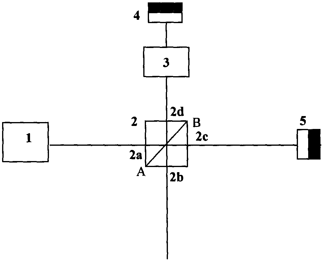
[0027] like figure 1 As shown, a high-speed, high-precision all-fiber polarization control device uses a laser (2) with an output center wavelength of 1310 nm, and the output light polarization state is +45° linearly polarized light, which is coupled into a four-port polarization beam splitter The input terminal 2a of the device (2). For the convenience of description, define the four-port polarization beam splitter (2) to reflect vertically polarized light |v〉, represented by Λ2; to transmit parallel state polarized light |h〉, represented by Λ1. After Λ1 is transmitted, it arrives at the 90° rotating Faraday reflector (5) by the 2c port and is reflected back. When it is reflected back by the 90° rotating Faraday reflector (5), its polarization direction is also rotated 90° to become a vertical polarization; The splitting surface of the four-p...


PUM


Abstract

The invention discloses a high-speed and high-precision all-fiber polarization control device which relates to the technical field of fiber polarization control, in particular relating to a device for realizing light polarization control through phase modulation, and aiming at designing a high-speed and high-precision all-fiber polarization control device which has the advantages of small volume, simple structure, strong anti-interference performance and easiness for realization. In the scheme, a main light path is formed by connecting a light source, a four-port light polarization beam splitter / combiner, a phase modulator and a 90-degree rotation Faraday reflection mirror. The output end of the light source is connected with the input end of the four-port light polarization beam splitter / combiner, the reflection port of the four-port light polarization beam splitter / combiner is sequentially connected with the phase modulator and the 90-degree rotation Faraday reflection mirror to form a control arm, and the transmission output end of the four-port light polarization beam splitter / combiner is connected with the 90-degree rotation Faraday reflection mirror to form a reference arm. The optical path of the control arm is strictly equal to that of the reference arm, and the control on the light polarization is realized by modulating the phase difference of the control arm and the reference arm through utilizing the phase modulator. Through combining the four-port light polarization beam splitter / combiner with the 90-degree rotation Faraday reflection mirror, the birefrigent effect of optical devices and fibers can be eliminated, and the stability and anti-interference capability of the system can be enhanced, and the high-speed phase modulator guarantees that the working frequency of the device reaches 109Hz.

Description

technical field [0001] The invention relates to the technical field of optical fiber polarization control, in particular to a device for realizing polarization control of light by using phase modulation. Background technique [0002] The polarization state of light is used more and more widely as a carrier of information, especially an important way for the realization of quantum key distribution. Secondly, in the coupling of single-mode fiber and optical waveguide, polarization matching is also one of the important methods to improve the coupling efficiency. The polarization state of light also has important applications in single-mode fiber sensors and fiber lasers. Therefore, the control of the polarization state of light, especially the high-precision and high-speed manipulation technology and device of the polarization state of light in optical fibers has attracted the attention of researchers and engineers. However, in ordinary optical fiber device systems, with the e...

Claims


Application Information

Patent Timeline
IPC IPC(8): G02B27/28
Inventor 马海强焦荣珍王川汪龙
Owner BEIJING UNIV OF POSTS & TELECOMM
Why Eureka
Eureka Blog
Learn More