Bidirectional isolation direct-current converter

A DC converter, two-way isolation technology, applied in the direction of converting DC power input to DC power output, and intermediate conversion to AC conversion equipment, instruments, etc., can solve problems such as small voltage conversion ratio, and achieve the effect of preventing faults

Active Publication Date: 2011-09-14
CHINA EPRI SCIENCE & TECHNOLOGY CO LTD +2
View PDF5 Cites 15 Cited by
  • Summary
  • Abstract
  • Description
  • Claims
  • Application Information

AI Technical Summary

Problems solved by technology

Based on the topology of bidirectional DC-DC converter, it is divided into non-isolated and isolated topology. For non-isolated DC-DC converter, although it can meet the application requirements of different power levels, and meet low voltage and high current applications, but the voltage conversion ratio is small, and the isolated DC-DC converter can achieve the required large voltage conversion ratio

Method used


Image

  • Bidirectional isolation direct-current converter
  • Bidirectional isolation direct-current converter
  • Bidirectional isolation direct-current converter

Examples


Embodiment 1

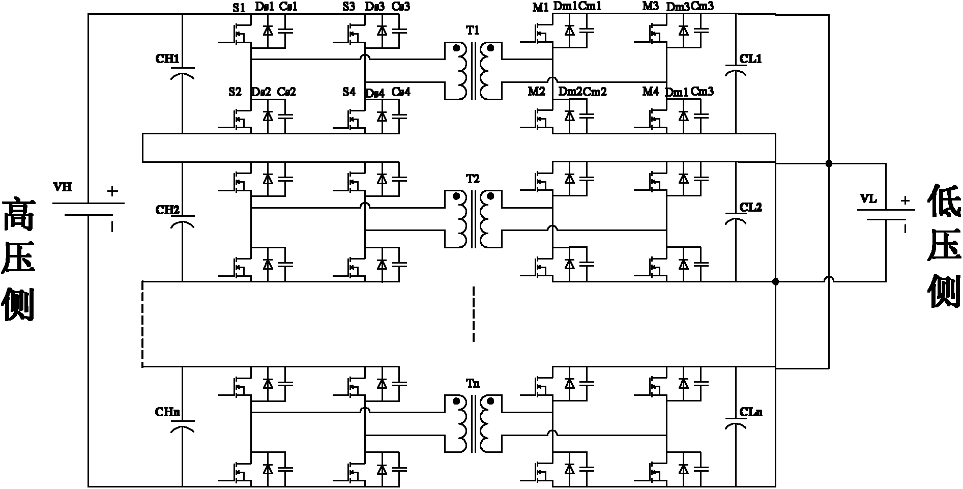
[0038] Figure 7 It is a specific embodiment of the symmetry of the modules on both sides provided by the present invention. It is a topology diagram of a 10kV DC system connected to a 1kV DC system; a 10kV DC system is connected to a 1kV DC system. The fully controlled power electronic device of each H bridge arm adopts 1700V / 800A IGBT;

[0039] All power modules on the DC low-voltage side on the right are connected in parallel, and each H-bridge can reach a withstand voltage of 1kV, so the current can reach 400A times 10, which is about 4000A;

[0040] In order to realize direct connection to the 10kV DC system on the left side of the DC high voltage side, 10 H bridges are required to be connected in series, so that each H bridge has an equal voltage of 1kV and a current of 400A on the high voltage side;

[0041] Such a system can be applied to the interconnection of two DC systems, and the transmission power can reach 4MW.

[0042]The above scheme can be applied to the d...

Embodiment 2

[0045] Figure 8 The specific embodiment of the asymmetry of the modules on both sides provided by the present invention is the topology diagram of the 35kV DC system connected to the 10kV DC system; comprehensively considering the function and protection of the DC converter, the fully-controlled power electronic device of each H-bridge arm on the left uses 6500V / 400A IGBT; the full-control power electronic device of each H-bridge arm on the right adopts 1700V / 800A IGBT;

[0046] Due to the high system voltage of the DC side power module on the left side, 10 H-bridges need to be connected in series, so that the average voltage of each H-bridge is 3.5kV, and the system current on the left side is 100A;

[0047] The power modules on the right DC side are all connected in series, and each H-bridge can reach a withstand voltage of 1kV. Due to power conservation, the current on the right side can reach 350A;

[0048] Such a system can be applied to the interconnection of two sets ...


PUM


Abstract

The invention relates to a bidirectional isolation direct-current converter which is connected into a direct-current system; the converter is formed by connecting at least one converting module; the converting module comprises two power modules, namely a DC / AC module and an AC / DC module; alternating-current sides of the DC / AC module and the AC / DC module are connected by a transformer T; direct-current sides of the DC / AC module and the AC / DC module are connected in parallel with capacitors C1 and C2; the direct-current sides of the DC / AC module are connected in series to form a direct-current high-voltage side; and the direct-current sides of the AC / DC module are connected in series or in parallel to form a direct-current low-voltage side. The bidirectional isolation direct-current converter realizes the DC-AC-DC power conversion and can be applied in the systems that require direct-current conversion; the converter can complete the conversion process from direct-current high voltage to direct-current low voltage in positive direction and can complete the conversion process from direct-current low voltage to direct-current high voltage in reverse direction, thus realizing bidirectional flow of energy.

Description

technical field [0001] The invention relates to a DC converter in the field of power electronics, in particular to a bidirectional isolated DC converter. Background technique [0002] In the AC system, the power modules include H full bridge, three-phase bridge, and the series-parallel technology of power modules is becoming more and more mature. Chain-link converters generally adopt the method of connecting power modules in series on the AC side to improve the withstand voltage level. At present, chain-link converters have been widely used in the fields of high-voltage frequency conversion and reactive power compensation; while power module parallel multiplexing technology is widely used in large-capacity transformers. Various occasions of converters, such as locomotive transmission, active filter field. [0003] The DC-DC converter is a technology that converts one kind of direct current into another form of direct current, and mainly realizes the conversion of voltage an...

Claims


Application Information

Patent Timeline
Patent Type & Authority Applications(China)
IPC IPC(8): H02M3/24H02M3/28
Inventor 郭剑波赵波訾振宁
Owner CHINA EPRI SCIENCE & TECHNOLOGY CO LTD
Why Eureka
Try Eureka