
Method for routing data centre network system

A data center network and routing technology, applied in data exchange networks, digital transmission systems, transmission systems, etc., can solve the problems of poor network configuration flexibility, complex network topology, and waste of port space, and achieve a simple and easy construction method. The effect of high network reliability and simple construction method

Inactive Publication Date: 2013-10-23
ZTE CORP
View PDF2 Cites 0 Cited by
  • Summary
  • Abstract
  • Description
  • Claims
  • Application Information

AI Technical Summary

Problems solved by technology

[0006] Although the above network structure solves the upper-layer bandwidth bottleneck problem of building a large-scale data center network, it still has the following disadvantages: (1) Due to the limitation of its topology structure, the oversubscription (Oversubscription) ratio of network traffic is difficult to be flexible according to actual needs (2) Its network topology is relatively complex, device addressing needs to follow strict and complex rules, and device ports are connected in strict order. Deployment is cumbersome, and network maintenance during operation is relatively difficult; (3) Due to the complex topology, its routing algorithm is relatively complex; (4) When building a small-scale data center network, there will be ports In the case of wasted space, the network scalability is poor

Method used


Image

  • Method for routing data centre network system
  • Method for routing data centre network system
  • Method for routing data centre network system

Examples


Embodiment Construction

[0020] In order to make the above objects, features and advantages of the present invention more comprehensible, the present invention will be further described in detail below in conjunction with the accompanying drawings and specific embodiments.

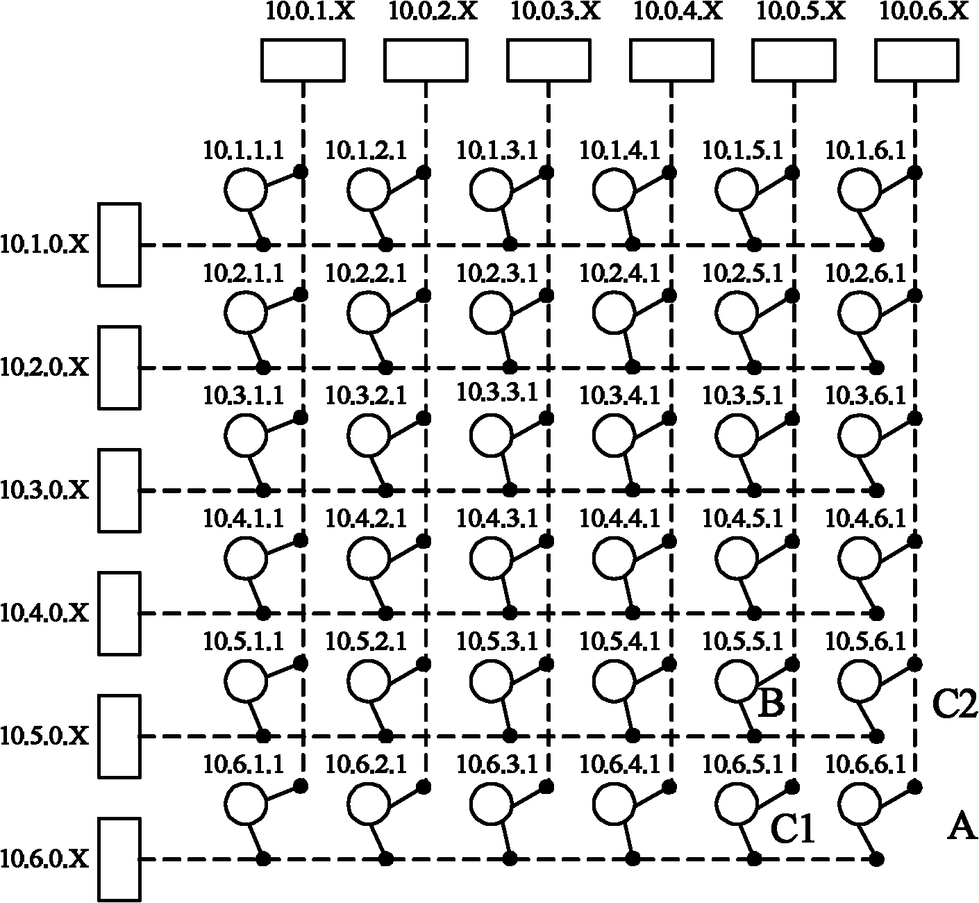
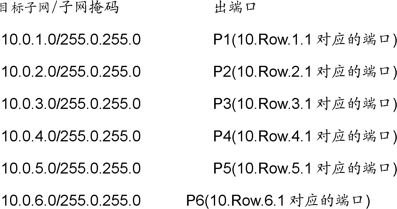
[0021] In the data center network system provided by the present invention, the network adopts a regular topology (switching matrix topology), and addressing is performed according to certain rules. The data center network system consists of a group of row head switches 10.Row.0.X, row head switches 10.0.Col.X, access switches 10.Row.Col.1 and various servers 10 connected to the access switches. Row.Col.X composition. Among them, Row is the row number of the row where the switch or server is located, and Col is the column number of the column where the switch or server is located; for the switch at the head of the row / column, 0<X≤255, and for the server, 1<X≤255. The subnet mask of all devices is set to 255.255.255.0.

[0022] T...


PUM


Abstract

The present invention relates to a routing method for a data center network system. The data center network system comprises row header switches, column header switches, and access switches arranged in an array. The row header of each row is provided with at least one row header switch. The column header of each column is provided with at least one column header switch. Servers are connected to the access switches. The access switches are connected to all row header switches of the row where the access switches are located and to all column header switches of the column where the access switches are located. In the present invention, the servers of a same subnet communicate therebetween via access switches connected thereto, and servers of different subnets need to communicate therebetween via the access switches, the row header switches, and the column header switches. The routing method employed in the present invention is simplified, efficient, allows for convenient implementation via hardware, and for great routing speed.

Description

technical field [0001] The invention relates to a routing method, in particular to a routing method for a data center network system. Background technique [0002] The data center is the provider center of various application services of the enterprise, and the center of data calculation, exchange and storage. It combines advanced network technology and storage technology, carries more than 80% of the service requests and data storage capacity in the network, and provides services and operating platforms for the healthy operation of customers' business systems. [0003] Data centers first appeared in the early 1960s. With the rapid construction of the Internet and the rapid development of information technology, the data center entered a period of vigorous development in the middle and late 1990s, and the construction scale and the number of servers increased at an alarming rate every year. The vigorous development of Internet technology has set off a climax in the constru...

Claims


Application Information

Patent Timeline
Patent Type & Authority Patents(China)
IPC IPC(8): H04L12/70H04L12/701
CPCH04L45/583
Inventor 孙延涛刘真方维维刘强
Owner ZTE CORP
Learn More