
Machine tool

A technology for processing machines and cutting tools, applied in metal processing, metal processing mechanical parts, metal processing equipment, etc., can solve the problems of high economic investment cost of processing machines, and achieve the effect of improving efficiency

Inactive Publication Date: 2011-09-21
GROB WERKE & K G
View PDF4 Cites 2 Cited by
  • Summary
  • Abstract
  • Description
  • Claims
  • Application Information

AI Technical Summary

Problems solved by technology

[0003] Known processing machines generally have high economic investment costs

Method used


Image

  • Machine tool
  • Machine tool
  • Machine tool

Examples


Embodiment Construction

[0032] In the figures, identical or mutually corresponding elements are each provided with the same reference numerals and are therefore not described again unless this is not the case.

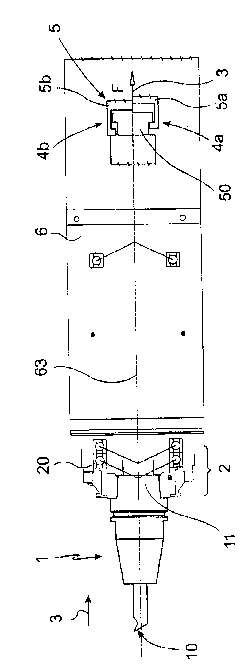
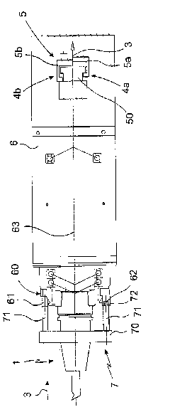
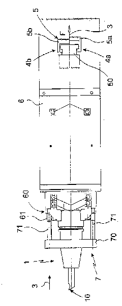
[0033] exist figure 1 , Figure 2a and image 3 In the right-hand area of ​​each figure, two different positions are respectively indicated and marked with the letters a and b. The configuration of the processing machine is suitable for realizing two fields of use or modes of use with the processing machine described here. For this purpose, in the tool spindle 6, especially on the side facing away from the machining tool 1 (on the figure 1 , Figure 2a , image 3 shown on the right in ), a separate drive is provided, the actuator of which has the reference number 5, which also designates the drive. The figures schematically show two different positions of the actuator 5 . The normal position 4 b is shown in the upper half 2 , which is situated above the central axis 63 , and the fixed ...


PUM


Abstract

A machine tool for machining work pieces. It has a machining tool. This is held in a tool mount. For that a tool clamping device is provided. An electric motor serves for generating the clamping power, or at least one means driven by the electric motor acts on a spring arrangement for effecting the release of the machining tool from the tool clamping device.

Description

technical field [0001] The invention relates to a processing machine for processing one or more workpieces, the processing machine comprising a processing tool which is held in a tool receptacle of a tool spindle of the processing machine indirectly or directly via a tool clamping device, and The tool clamping device has at least one tool clamping element which interacts indirectly or directly with the machining tool. Background technique [0002] Similar processing machines have long been known in metal processing, in particular metal cutting. Here, the machining tool is held by the tool spindle. The tool spindle is usually used to drive the machining tool in rotation and to position the machining tool in a desired position on the workpiece. The tool spindle therefore also has at least one degree of freedom of movement. However, the term "tool spindle" below is not restricted to be understood as a self-rotating drive of the machining tool, but does not limit the use of t...

Claims


Application Information

Patent Timeline
Patent Type & Authority Applications(China)
IPC IPC(8): B23Q1/52B23Q5/10B23Q3/00B23Q1/25
CPCB23Q1/70B23B2260/062B23B2270/60B23B31/261B23B2260/008B23B31/28Y10T409/309408B23Q5/04B23C1/06
Inventor B·格鲁博A·霍贝尔
Owner GROB WERKE & K G
Learn More