Device for dredging sludge by dredger
A technology for dredgers and cutter suction dredgers, which is applied in the directions of earth movers/shovels, mechanically driven excavators/dredgers, and construction, etc. problems, to achieve the effect of reducing manpower and material expenditure, reducing equipment and personnel investment, and simplifying process flow
Inactive Publication Date: 2011-09-21
YUNNAN DAHONGSHAN PIPELINE
View PDF4 Cites 8 Cited by
- Summary
- Abstract
- Description
- Claims
- Application Information
AI Technical Summary
Problems solved by technology
On the one hand, due to the large number of equipment and construction personnel, the corresponding production costs are also high. On the other hand, each step of suction, excavation, and transportation has a short time, which more or less affects the processes of the upper and lower levels, resulting in low productivity
In addition, because the dredging site is too far away from the shore or the mud discharge field, it cannot be directly transported to the accumulation point of the silt on the shore through the pressure pump, which exceeds the discharge distance of the general dredger, and can only be transported back and forth by traditional transport ships. , the capacity of the transport barge is limited, and the round-trip time difference has become an important factor limiting the efficiency of the dredger operation
It not only lengthens the construction period but also increases a large amount of engineering costs. This disadvantage is currently a problem widely encountered in the dredging of large lakes in China.
Method used
View moreImage
Smart ImageViewing Examples

Examples
Embodiment Construction
Login to view more PUM
 Abstract
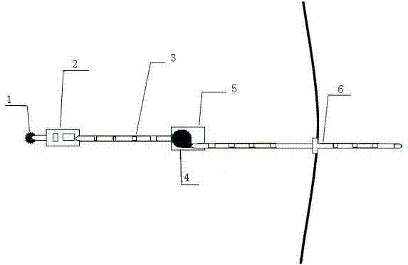
The invention relates to a device for dredging sludge by a dredger. The device comprises a suction dredger which is used for transmitting the sludge in a riverway or a lake into a port of a waterborne floating tube through a sludge suction pump; the other port of the waterborne floating tube is communicated with a shore tube bridged over the land; the device is characterized in that: the length of the waterborne floating tube is limitless and the waterborne floating tube consists of a plurality of sections; and any two adjacent sections of the waterborne floating tube are connected with each other through a booster pump. In the device, as the waterborne pressurization of the booster pump is assorted with the suction dredger, the extraction and the transportation of sludge form line production; therefore, the process flow is simplified, the investment of equipment and labor is reduced, and most importantly, the working efficiency of engineering is improved greatly and the daily management work and the construction cost are reduced at the same time; and secondary pollution of barge transportation to the periphery environment can be avoided.
Description
Device for dredging sludge through dredger Technical field The invention relates to a lake sediment dredging and conveying device, in particular to a device for dredging sludge through a dredger. Background technique The sludge removal of existing lakes or rivers is usually done by dredgers. In conventional construction methods, grab suction dredgers, dredgers and a certain number of transport barges need to be used for supporting construction. On the one hand, due to the large number of input equipment and construction personnel, the corresponding production cost is also high. On the other hand, each step of suction, digging and transportation has a shorter time, which more or less affects the superior and subordinate processes, resulting in Low operating rate. In addition, because the dredging site is too far away from the shore or the mud yard, it cannot be directly transported to the accumulation point of the silt on the shore by the pressure pump, so it exceeds the row ...
Claims
Login to view more Application Information
Patent Timeline
 Patent Type & Authority Applications(China)
IPC IPC(8): E02F5/28E02F3/88E02F3/90E02F7/10
Inventor 李幼灵安建普光跃潘春雷黄朝兵瞿承中苏靖翔王健拔海波
Owner YUNNAN DAHONGSHAN PIPELINE
- R&D Engineer
- R&D Manager
- IP Professional
Why Eureka
- Industry Leading Data Capabilities
- Powerful AI technology
- Patent DNA Extraction
Try Eureka
Browse by: Latest US Patents, China's latest patents, Technical Efficacy Thesaurus, Application Domain, Technology Topic.
© 2024 PatSnap. All rights reserved.Legal|Privacy policy|Modern Slavery Act Transparency Statement|Sitemap