Surface soil compacting roller with bionic geometric structure

A technology of geometric structure and pressure roller, applied in the field of soil pressure roller and agricultural machinery tillage parts, can solve the problems of increasing soil disturbance and damage, generating clods, reducing work efficiency, etc.

Active Publication Date: 2014-06-18
JILIN UNIV
View PDF15 Cites 0 Cited by
  • Summary
  • Abstract
  • Description
  • Claims
  • Application Information

AI Technical Summary

Problems solved by technology

However, when such a pressure roller works, it is easy to stick the soil on the surface of the seed, which increases the disturbance and damage to the soil, causes serious soil moisture loss, affects the germination and growth of the seed, and increases the working resistance when the adhesion phenomenon is serious. When necessary, it needs to be shut down for cleaning, which reduces the operating efficiency
In addition, when sowing, it is easy to cause a large number of soil clods, coupled with the influence of stubble and weeds, the seeds cannot be in good contact with the surrounding soil

Method used


Image

  • Surface soil compacting roller with bionic geometric structure
  • Surface soil compacting roller with bionic geometric structure
  • Surface soil compacting roller with bionic geometric structure

Examples


Embodiment 1

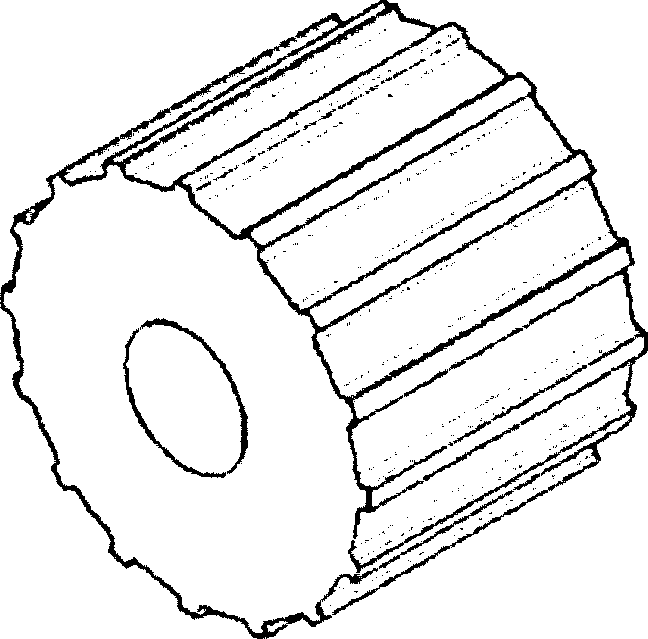
[0051]Referring to Fig. 1(a), the surface soil suppression roller with bionic geometric structure has a geometric structure of continuous ribs distributed along the roller alignment. The rib height is 5mm-50mm, the width is 10mm-50mm, and the rib spacing is 0mm-50mm; Carbon steel material, bionic geometry adopts ultra-high molecular weight polyethylene material or enamel coating material; grooves are dug out on the surface of the pressure roller base.

[0052] Refer to Fig. 1(b), Fig. 1(c), Fig. 1(d), Fig. 1(e), Fig. 1(f), Fig. 1(g). shape, convex sinusoidal, triangular or corrugated.

Embodiment 2

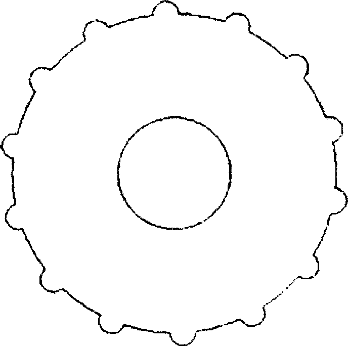
[0054] Refer to Fig. 1(h), Fig. 1(i), Fig. 1(j), the surface soil suppression rollers with bionic geometry structure, uniformly distributed, staggered and randomly distributed geometric structure of intermittent ribs along the roller alignment, the height of the ribs is 5mm~ 50mm, width 10mm~50mm, length 10mm~100mm, evenly distributed or staggered distributed rib-shaped structure with a rib spacing of 5mm~50mm; the substrate is made of cast iron or low carbon steel, and the bionic geometry is made of ultra-high molecular weight polymer. Vinyl or enamel-coated material; grooves are dug into the surface of the roller base.

[0055] Refer to Fig. 1(b), Fig. 1(c), Fig. 1(d), Fig. 1(e), Fig. 1(f), the cross-sectional profile of the rib adopts rectangle, circular arc, convex parabola, convex sinusoidal or triangle.

Embodiment 3

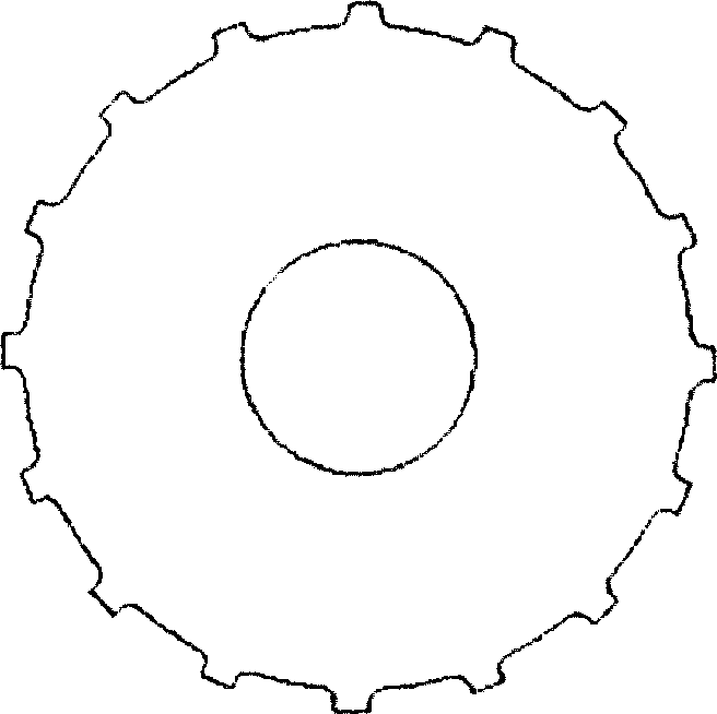
[0057] Referring to Fig. 2(a), the surface soil suppression roller with bionic geometric structure has a geometric structure of continuous ribs distributed along the circumference of the roller. Carbon steel material, bionic geometry adopts ultra-high molecular weight polyethylene material or enamel coating material; grooves are dug out on the surface of the pressure roller base.

[0058] Refer to Fig. 1(b), Fig. 1(c), Fig. 1(d), Fig. 1(e), Fig. 1(f), the cross-sectional profile of the rib adopts rectangle, circular arc, convex parabola, convex sinusoidal or triangle.


PUM


Abstract

The invention relates to a surface soil compacting roller with a bionic geometric structure, belonging to the field of agricultural machinery. By using the surface soil compacting roller, the problems that soil adheres when the compacting roller operates can be solved, and frictional acting force between the surface of the compacting roller and the contacted soil is regulated so as to regulate the compactness of the compacted soil, improve operation quality, save operation energy consumption and improve operation efficiency. In the surface soil compacting roller, structure along the alignment of the compacting roller or circumferentially continuous structure or interrupted rib-shaped structure is adopted; in the interrupted rib-shaped structure, even distribution, staggered distribution or random distribution is adopted, rib height is 5-50mm, height is 10-50mm, the length of the interrupted rib structure is 10-100mm, rib space between the continuous rib structure and even-distributed or staggered-distribution interrupted rib-shaped structure is 0-50mm; and the upper contour of the rib cross section adopts rectangle, circular arc, convex parabola shape, convex sinusoid, triangle or waviness.

Description

technical field [0001] The invention relates to an agricultural machinery tillage part for compacting soil, in particular to a soil pressing roller with a bionic geometric structure surface, which belongs to the field of agricultural machinery. Background technique [0002] The pressing roller is a commonly used agricultural machine. Its main function is to suppress the soil, especially the soil after sowing, so that the seeds are in close contact with the soil, prevent the soil moisture from being lost too quickly, protect the soil moisture, and facilitate seed germination and emergence. tidy. Soil suppression is an important link in crop production and one of the important factors affecting crop yield. The shape of the existing pressure roller is a spinning body, which is traditionally cylindrical, and the cylinder is placed horizontally to become a pressure roller, and its material is mostly cast iron or low-carbon steel. However, when such a pressure roller works, it i...

Claims


Application Information

Patent Timeline
Patent Type & Authority Patents(China)
IPC IPC(8): A01B29/00
Inventor 佟金张清珠陈东辉孙霁宇陈玉香马云海贾洪雷周江
Owner JILIN UNIV
Why Eureka
Try Eureka