Front-end structure for a motor vehicle

A body and automobile technology, applied in the front-end field of automobile body, can solve the problems of high space occupancy rate, large weight, high manufacturing cost, etc., and achieve high anti-collision safety effect

Inactive Publication Date: 2011-10-05
GM GLOBAL TECH OPERATIONS LLC
View PDF6 Cites 4 Cited by
  • Summary
  • Abstract
  • Description
  • Claims
  • Application Information

AI Technical Summary

Problems solved by technology

However, the construction of radiators and condensers with a large heat dissipation area re

Method used


Image

  • Front-end structure for a motor vehicle
  • Front-end structure for a motor vehicle
  • Front-end structure for a motor vehicle

Examples


Embodiment Construction

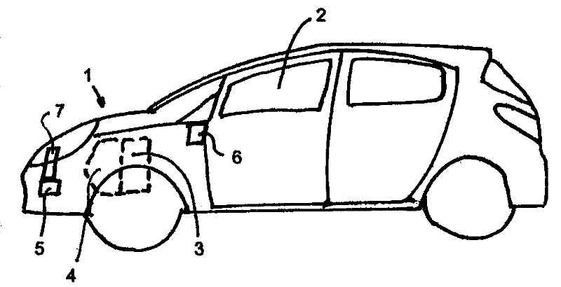
[0018] figure 1 The motor vehicle shown has a front end 1 pointing in the direction of travel and a passenger compartment 2 arranged behind the front end 1 . An engine block 3 with an internal combustion engine 4 and a radiator 5 for the internal combustion engine 4 are located in the front end 1 . In addition, the motor vehicle has an air-conditioning system 6 for the passenger compartment 2 . The condenser 7 of the air-conditioning system 6 is arranged in the end of the front body 1 pointing in the direction of travel.

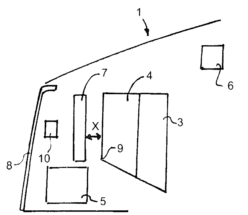
[0019] figure 2 show figure 1 A longitudinal section of the front end 1 is shown, the front end 1 being bounded by a radiator grille 8 in the direction of travel. The radiator 5 of the internal combustion engine 4 and the condenser 7 of the air-conditioning system 6 are located vertically one above the other behind the radiator grille 8 . The condenser 7 is configured as a plate and placed above the radiator 5 . The radiator 5 has a substantially squa...


PUM


Abstract

A front structure 1 for a motor vehicle includes a radiator 5 of an internal combustion engine 4 and a condenser 7 of an air conditioning system 6 arranged vertically on top of each other. The radiator 5 is substantially square shaped and is located below an edge 9 of the internal-combustion engine 4, pointing in driving direction. The front end structure 1 has a low weight and a low centre of gravity. A mutual influence between the radiator 5 and the condenser 7 is avoided.

Description

technical field [0001] The invention relates to a front body of a motor vehicle with a condenser arranged at its end pointing in the direction of travel for an air conditioning system and a radiator for an internal combustion engine of the motor vehicle. Background technique [0002] Such front ends are frequently used in today's motor vehicles and are already known from practice. In this known front end, the condenser of the air-conditioning system and the radiator of the internal combustion engine form a structural unit. [0003] Such a structural unit consisting of a condenser of an air-conditioning system and a radiator of an internal combustion engine is known, for example, from DE 689 05 753 T2. In this case, the condenser and the radiator are arranged one behind the other in the direction of travel and are each configured as a plate transversely to the direction of travel. Such a structural unit can be mounted directly behind a radiator grille pointing in the direct...

Claims


Application Information

Patent Timeline
IPC IPC(8): B60K11/04B60H1/00
CPCB60K11/04B60H1/32B62D25/082
Inventor 克劳斯.斯泰勒
Owner GM GLOBAL TECH OPERATIONS LLC
Why Eureka
Try Eureka