
Imaging adjustment unit and focusing and leveling control system using the unit

A technology of adjusting unit and imaging unit, applied in the field of control system, can solve the problem of difficult installation, and achieve the effects of simple design, strong space adaptability, and convenient installation

Inactive Publication Date: 2011-10-05
SHANGHAI MICRO ELECTRONICS EQUIP (GRP) CO LTD
View PDF3 Cites 8 Cited by
  • Summary
  • Abstract
  • Description
  • Claims
  • Application Information

AI Technical Summary

Problems solved by technology

[0005] The present invention proposes an imaging adjustment unit and a focusing and leveling control system using it, which can solve the above-mentioned problem of difficult installation and simplify its own structure without changing the imaging accuracy

Method used


Image

  • Imaging adjustment unit and focusing and leveling control system using the unit
  • Imaging adjustment unit and focusing and leveling control system using the unit
  • Imaging adjustment unit and focusing and leveling control system using the unit

Examples


Embodiment Construction

[0021] In order to better understand the technical content of the present invention, specific embodiments are given and described as follows in conjunction with the accompanying drawings.

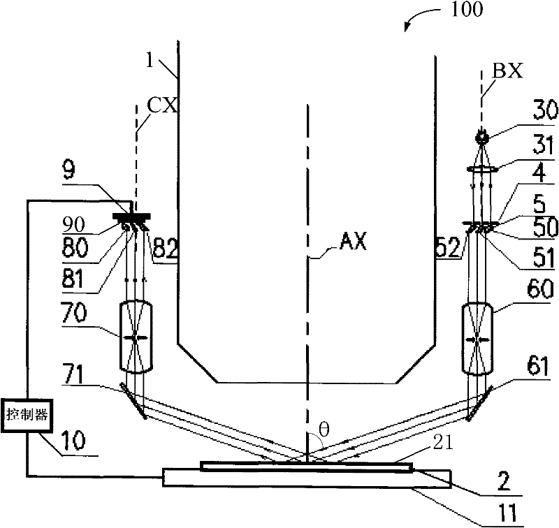
[0022] figure 1 Shown is a schematic structural diagram of the projection lithography machine according to the first embodiment of the present invention.

[0023] Please refer to figure 1 . The projection lithography machine 100 includes a projection objective lens 1 , a silicon wafer 2 and a workpiece stage 11 . The projection objective lens 1 is placed along the first optical axis AX, and is used for performing photolithography on the silicon wafer 2 . The silicon wafer 2 is placed on the workpiece table 11 , the silicon wafer surface 21 of the silicon wafer 2 is perpendicular to the optical axis AX, and the silicon wafer surface 21 is located on the best focal plane of the projection objective lens 1 . The workpiece table 11 is driven by the workpiece table motion system (not shown) ...


PUM


Abstract

The invention puts forward an imaging adjustment unit and a focusing and leveling control system using the unit. The focusing and leveling control system comprises a lighting unit, a marking plate, a projection imaging unit, a detector and a controller. The lighting unit generates light beams which pass through a plurality of marks on the marking plate so as to form multiple incident rays projecting images on a silicon chip surface, so that several marked projections come into being. And the marked projections are reflected by the silicon chip surface, thus forming multiple reflected rays projecting images on the detector which controls the movement of a workpiece table. And the imaging adjustment unit includes a first imaging adjustment unit located in the optical path of the incident rays and a second imaging adjustment unit located in the optical path of the reflected rays. Wherein, the first imaging adjustment unit adjusts the optical length of the incident rays for focusing them simultaneously on the silicon chip surface, and the second imaging adjustment unit adjusts the optical length of the reflected rays for focusing them simultaneously on the detection surface of the detector. The imaging adjustment unit provided in the invention has a simple structure and is convenient for installation.

Description

technical field [0001] The invention relates to a control system, and in particular to a control system for adjusting silicon wafers in a photolithography machine, and an imaging adjustment unit included in the control system is also involved. Background technique [0002] The projection lithography machine is a device used to project the pattern on the mask onto the surface of the silicon wafer through the projection objective lens. In the projection exposure equipment, there must be an automatic focusing and leveling control system to accurately set the surface of the silicon wafer to the designated exposure position. [0003] There are many different technical solutions for realizing the automatic focusing and leveling control function. At present, the non-contact photoelectric measurement technology is more commonly used, in which the optical part of the measurement system adopts an optical structure that satisfies oblique imaging. The main purpose is to make the focus ...

Claims


Application Information

Patent Timeline
IPC IPC(8): G03F9/00
Inventor 张冲李志丹陈飞彪
Owner SHANGHAI MICRO ELECTRONICS EQUIP (GRP) CO LTD
Learn More