
Alignment system and alignment method for photolithographic device

An alignment system and lithography technology, applied in photolithography exposure devices, microlithography exposure equipment, optics, etc., can solve problems such as low contrast of scanning signals, reduced fitting efficiency, and complex subsequent signal processing

Inactive Publication Date: 2011-10-05
SHANGHAI MICRO ELECTRONICS EQUIP (GRP) CO LTD +1
View PDF5 Cites 10 Cited by
  • Summary
  • Abstract
  • Description
  • Claims
  • Application Information

AI Technical Summary

Problems solved by technology

The above-mentioned alignment system for lithography devices can reduce the problems of low contrast of scanning signals caused by marks, reduced fitting efficiency due to large scanning lengths, and more complicated subsequent signal processing.

Method used


Image

  • Alignment system and alignment method for photolithographic device
  • Alignment system and alignment method for photolithographic device
  • Alignment system and alignment method for photolithographic device

Examples


Embodiment Construction

[0031] In order to better understand the technical content of the present invention, specific embodiments are given together with the attached drawings for description as follows.

[0032] Figure 4 Shown is a schematic structural view of an alignment system for a lithographic apparatus according to an embodiment of the present invention. The alignment system for a lithography apparatus provided by the present invention is used to realize the alignment between a workpiece stage and a mask or between a workpiece stage and a mask stage. Such as Figure 4 As shown, an alignment system 1 for a lithography apparatus includes a light source module 10 , an illumination module 11 , a mask 12 , a mask table 13 , an objective lens module 14 , a detection module 15 and a workpiece table 16 .

[0033] In this embodiment, the light source module 10 may be a DUV light source or a UV light source, which is not limited in the present invention. In addition to being used for exposure, the l...


PUM


Abstract

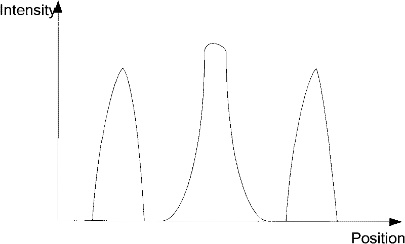
The invention provides an alignment system and an alignment method for a photolithographic device, which are used for implementing alignment of a work piece table and a mask or of the work piece table and a mask table. The alignment system for the photolithographic device comprises a light source module, an objective lens module, a detection module, an alignment mark and a reference mark. The alignment mark is arranged at the mask or the mask table, and comprises a first square mark for coarse alignment and a first grating mark for fine alignment. The reference mark is arranged at the work piece table, and comprises a second square mark for coarse alignment and a second grating mark for fine alignment. The alignment mark in the alignment system has extremely high contrast ratio in a small scanning range, so that the signal-to-noise ratio of scanning signals is greatly improved, post treatment on the scanning signals is simplified and efficiency is improved.

Description

technical field [0001] The present invention relates to lithography alignment technology, and in particular to an alignment system and an alignment method for a lithography apparatus. Background technique [0002] Lithography equipment is mainly used in the manufacture of integrated circuits IC or other micro-devices. During the manufacturing process, a complete chip usually requires multiple photolithography exposures to complete. During these exposures, the alignment accuracy between the wafer and the wafer stage is an important factor affecting the lithography accuracy. Existing lithography devices usually adopt two alignment schemes, one is through-the-lens TTL alignment technology, and the other is OA off-axis alignment technology. [0003] In the TTL alignment technology, the alignment mark on the mask is first illuminated by laser to make it image on the silicon wafer plane, and then the workpiece table is moved so that the reference mark on the work table scans the...

Claims


Application Information

Patent Timeline
IPC IPC(8): G03F9/00G03F7/20
Inventor 胡明辉李运锋
Owner SHANGHAI MICRO ELECTRONICS EQUIP (GRP) CO LTD
Learn More