MEMS (micro electro mechanical system) microphone chip and manufacture method thereof

A manufacturing method and microphone technology, which are applied to sensors, electrostatic transducers, microphones, electrical components, etc., can solve the problems of increasing the cutting cost of MEMS chip units, difficulty in etching the substrate thickness, and being unsuitable for mass production. The effect of easy process, improved yield and improved efficiency

Active Publication Date: 2011-10-05
GOERTEK MICROELECTRONICS CO LTD
View PDF5 Cites 2 Cited by
  • Summary
  • Abstract
  • Description
  • Claims
  • Application Information

AI Technical Summary

Problems solved by technology

For MEMS chips with this structure, there are mainly two cutting processes, one is water cutting, which is relatively cheap, but the vibration film and other areas in the parallel plate capacitor are very fragile and are easily contaminated during the cutting process; Another cutting process is laser cutting. Laser cutting can avoid the problem of contamination of MEMS chips, but the cost is very high and it is not suitable for mass production.
[0005] Moreover, in the MEMS chip manufacturing process, the through-holes in the substrate need to be formed by an etching process, and the problem of the large thickness of the substrate also brings difficulties to the etching process, resulting in low etching efficiency and low yield of MEMS chips; in addition, MEMS In the chip manufacturing process, the substrate is also required to have a certain thickness to prevent the chip from being damaged or broken, which further increases the cutting cost of the MEMS chip unit and reduces the cutting efficiency.

Method used


Image

  • MEMS (micro electro mechanical system) microphone chip and manufacture method thereof
  • MEMS (micro electro mechanical system) microphone chip and manufacture method thereof
  • MEMS (micro electro mechanical system) microphone chip and manufacture method thereof

Examples


no. 1 example

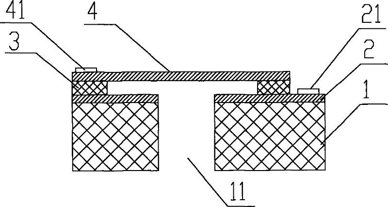
[0035] image 3 It is a configuration diagram showing the MEMS microphone chip according to the first embodiment of the present invention. Such as image 3 As shown, the MEMS microphone chip includes a base 1, the base 1 is provided with a hole 11 through up and down, and a parallel plate capacitor composed of a fixed plate 2, an isolation layer 3 and a vibrating membrane 4 is provided above the base, in the parallel plate capacitor The vibrating membrane 4 can receive external sound signals from above or below and vibrate, so that the parallel plate capacitor generates an electric signal to realize the sound-to-electricity conversion function. A metal connection point 21 is arranged on the fixed pole plate 2, and a metal connection point 41 is arranged on the vibrating membrane 4, and the connection points 21 and 41 can lead out two electrodes of the parallel plate capacitor respectively. Moreover, a protection device 5 is provided on the side of the parallel plate capacito...

no. 2 example

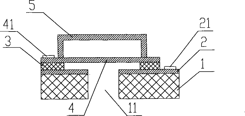
[0048] Figure 6 It is a configuration diagram showing the MEMS microphone chip according to the second embodiment of the present invention. Such as Figure 6 As shown, the MEMS microphone chip includes a base 1, the base 1 is provided with a hole 11 through up and down, and a parallel plate capacitor composed of a fixed plate 2, an isolation layer 3 and a vibrating membrane 4 is arranged above the base, and the fixed plate 2 A metal connection point 21 and a metal connection point 41 for leading out the two electrodes of the parallel plate capacitor are respectively arranged on the vibrating film 4, and are arranged on the side opposite to the substrate 1 of the parallel plate capacitor and above the vibrating film 4 There is a protection device 5, which is used to separate structures such as relatively fragile vibrating membranes in the parallel plate capacitor from the external space of the MEMS microphone chip, so as to prevent the MEMS microphone chip from being polluted...

no. 3 example

[0051] Figure 7 is a configuration diagram showing a MEMS microphone chip according to a third embodiment of the present invention. Such as Figure 7 As shown, the MEMS microphone chip includes a base 1, the base 1 is provided with a hole 11 through up and down, and a parallel plate capacitor composed of a fixed plate 2, an isolation layer 3 and a vibrating membrane 4 is arranged above the base, and the fixed plate 2 A metal connection point 21 and a metal connection point 41 for leading out the two electrodes of the parallel plate capacitor are respectively arranged on the vibrating film 4, and are arranged on the side opposite to the substrate 1 of the parallel plate capacitor and above the vibrating film 4 There is an annular support ring 52 and a flat plate 53 . The annular support ring 52, the flat plate 53 and the diaphragm form a protective structure capable of sealing the diaphragm 4, which is used to separate structures such as the relatively fragile diaphragm in t...


PUM


Abstract

The invention provides an MEMS (micro electro mechanical system) microphone chip and a manufacture method thereof. The MEMS microphone chip comprises a substrate and a parallel plate capacitor arranged on the substrate, wherein one side of the parallel plate capacitor is opposite to the substrate; and the outer part of the other side of the parallel plate capacitor is provided with a protective device for protecting the main body structure of the MEMS microphone chip. In the MEMS microphone chip, a vibrating diaphragm is provided with the protective device so as to separate structures, such as tender vibrating diaphragms and the like in the parallel plate capacitor from the outer space of the MEMS microphone chip, so that the MEMS microphone chip can be prevented from being polluted in the cutting process so as to effectively improve manufacture process efficiency, lower production cost and improve production yield; and in addition, the chip can be fully protected in the subsequent installing and using process of the MEMS microphone chip.

Description

technical field [0001] The invention relates to a microphone chip and a manufacturing method thereof, in particular to a MEMS microphone chip and a manufacturing and packaging method thereof. Background technique [0002] In recent years, with the continuous reduction in volume and higher performance of electronic products such as mobile phones and notebooks, correspondingly, the volume of supporting electronic components is continuously reduced, and the performance and consistency are improved, and the use of MEMS (micro-electromechanical systems) ) process-integrated MEMS microphones have begun to be applied in batches to electronic products such as mobile phones and notebooks. Against this backdrop, the demand for MEMS microphones produced using MEMS process technology is rapidly increasing. A core device of the MEMS microphone is the MEMS microphone chip made by MEMS technology, which can complete the sound-to-electricity conversion function. [0003] figure 1 It is a...

Claims


Application Information

Patent Timeline
Patent Type & Authority Applications(China)
IPC IPC(8): H04R19/04H04R31/00
Inventor 蔡孟锦
Owner GOERTEK MICROELECTRONICS CO LTD
Why Eureka
Try Eureka