Carrier tape feeder

一种送料器、载带的技术,应用在电气元件、金属加工设备、电气元件等方向,能够解决降低工作效率、作业时间加长、改变载带节距等问题,达到提高工作稳定性、次品发生率低、提高适应能力的效果

Inactive Publication Date: 2011-10-05
STS
View PDF6 Cites 46 Cited by
  • Summary
  • Abstract
  • Description
  • Claims
  • Application Information

AI Technical Summary

Problems solved by technology

In the above state where the carrier tape is exhausted, the process of reloading the carrier tape reel cannot maintain the continuity of the operation, which not only results in a longer working time, but also in order to confirm whether the carrier tape is exhausted, the staff needs to check the supply of the carrier tape from time to time state, reducing work efficiency
[0005] In addition, the general carrier tape feeder is designed to discharge the base tape and cover tape separately after the cover tape is completely separated from the base tape of the carrier tape. The pitch of the carrier tape makes it impossible to accurately pick up (Pick-up) parts
In particular, when multiple tape feeders are installed on the placement machine, the cover tapes discharged from the respective carrier tapes installed on each tape feeder may become entangled or rub against each other, causing more serious static electricity problems. Eventually, the rate of defective products will increase, and the working hours will be prolonged, which will have a fatal impact on production efficiency.

Method used


Image

  • Carrier tape feeder
  • Carrier tape feeder
  • Carrier tape feeder

Examples


Embodiment Construction

[0074] The present invention will be described in detail below.

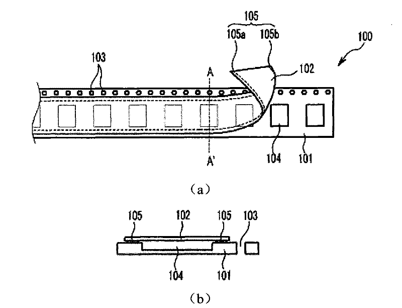
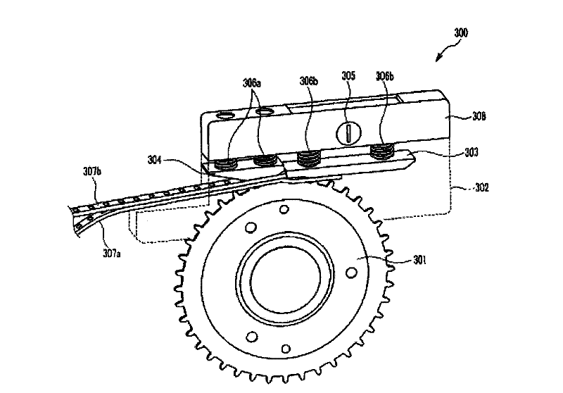
[0075] The carrier tape feeder of the present invention includes: a carrier tape loading part, a component pick-up part, and a drive part, wherein the part pick-up part includes: a knife edge part, which separates the base tape and the cover tape at the first joint part; the folding part, The folded portion is formed at intervals on the side of the blade portion, and the folded portion is formed by folding the cover tape separated from the blade portion along the length direction in a state combined with the second joint portion; a guide portion, which is laminated on the on the base tape, and extend obliquely from the blade portion and the folded portion to the outside of the carrier tape, to guide the upper and lower surfaces of the cover tape folded at the folded portion to turn over and be stacked on the base tape; wherein, the folded portion opposite to the blade portion Terminations of the sides extend abo...


PUM


Abstract

A carrier tape feeder is provided. The carrier tape feeder includes a unit for loading a carrier tape, a picking-up unit and a driving unit. The pick-up unit includes a knife portion, a folding-guiding portion, and an inversion-guiding portion. The knife portion separates a cover tape from a base tape in a first adhesive portion. The folding-guiding portion is spaced from one lateral side of the knife portion to induce folding of the cover tape separated by the knife portion in the lengthwise direction in a state in which the cover tape is partially attached to the base tape in a second adhesive portion. The inversion-guiding portion extends in an oblique direction from the knife portion and the folding-guiding portion toward the outside of the carrier tape to induce inversion of the upper and lower surfaces of the cover tape folded in the folding-guiding portion so as to be superimposed on the base tape. The distal end of the lateral side of the folding-guiding portion opposed to the knife portion extends above the second adhesive portion.

Description

technical field [0001] The present invention relates to a carrier tape feeder, and more particularly, to a carrier tape feeder capable of continuously supplying a carrier tape to a mounter. Background technique [0002] Chip mounter is a kind of vacuum adsorption of electronic components supplied by the feeder through the nozzle of the pick-up head, and then mounts the electronic components on the printed circuit board at high speed and high precision. equipment at the installation location. Recently, with the diversification of functions of electronic equipment, the improvement of configuration, and the miniaturization of products, high-density component assembly of printed circuit boards built in electronic equipment is required. The component mounting technology of the printed circuit board has also gradually changed from the previous through-hole method to the surface mount technology (Surface mounted technology, SMT) that directly performs high-density assembly on the ...

Claims


Application Information

Patent Timeline
Patent Type & Authority Applications(China)
IPC IPC(8): H05K13/02
CPCH05K13/0084H05K13/0417H05K13/0215H05K13/0419Y10T156/1978Y10T225/22
Inventor 黄永洙金勇成朴受弘金喜钟
Owner STS
Why Eureka
Try Eureka