Implementation method for self-starting and stopping control system of machine set

A technology of a control system and an implementation method, applied in the direction of program control, electrical program control, etc. in a sequence/logic controller, can solve the problems of increased debugging workload, increased configuration and debugging work, inflexibility, etc. The effect of thermal control automation level, improving debugging efficiency and increasing flexibility

Active Publication Date: 2011-10-12
SHANGHAI POWER EQUIP RES INST
View PDF3 Cites 26 Cited by
  • Summary
  • Abstract
  • Description
  • Claims
  • Application Information

AI Technical Summary

Problems solved by technology

The design and determination of the control logic takes about 1 to 2 months. This conventional approach is difficult to complete the design work of the APS system with a huge workload
This is also one of the reasons why domestic APS is difficult to achieve
[0004] 2. Increase the workload of debugging
[0005] 3. It is inconvenient to modify the function group
Because the function group is composed of a series of step instructions in sequence, if you need to add a step, you need to delay the subsequent breakpoint or device group step instruction configuration by one step, which is very inflexible
[0006] 4. It is not conducive to the APS function transformation of the units already in operation
For the units that have been put into operation, the driver level and some function groups have been debugged and put into use. Adding APS functions according to the previous method requires modifying the logic of all existing device drivers, which greatly increases the work of configuration and debugging. In addition, limited units Overhaul time makes it impossible to realize the APS control of the units in operation

Method used


Image

  • Implementation method for self-starting and stopping control system of machine set
  • Implementation method for self-starting and stopping control system of machine set
  • Implementation method for self-starting and stopping control system of machine set

Examples


Embodiment

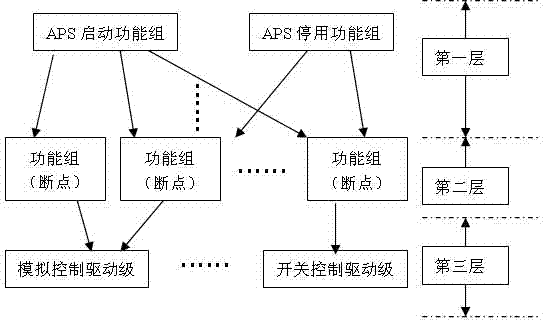
[0025] The invention provides a programming method to realize the APS function. The specific scheme is as follows: on the basis of the original third layer of APS, that is, the device driver level or part of the sequential control function group, the third layer configuration content is not changed, and the second layer breakpoint layer and the first layer APS function are realized by programming. Group functions.

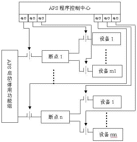
[0026] like image 3 As shown, the content of the invention is the APS program control center in the box, which is realized by programming, without adding actual configuration, and directly uses the program instead of the operator to issue instructions to complete the function. figure 1 The methods implemented in the first layer and the second layer are similar, but the calling objects are different.

[0027] The method for realizing the self-starting and stopping control system of the unit provided by the present invention uses the APS program control center to ...


PUM


Abstract

The invention provides an implementation method for a self-starting and stopping control system of a machine set, and the method is characterized by comprising the following steps: firstly, receiving starting signals or stopping signals through the function set which is positioned at a first layer; then, sequentially judging whether the permissive conditions of the starting are met or not or the permissive conditions of the stopping are met or not, whether initialization signals exist or not, whether interruption signals exist and whether feedback signals exist; and then, starting to implement a breakpoint layer which is positioned at a second layer, wherein the implementation command of the second layer is the same as that of the first layer. Compared with the existing method, the methodprovided by the invention has the following advantages: 1, the dependence on the driving stage of equipment can be greatly reduced, and the debugging efficiency is enhanced; 2, the modification flexibility of a function set is increased; and 3, the implementation method provided by the invention is also suitable for a commissioning machine set.

Description

technical field [0001] The invention relates to a distributed control technology of a thermal power unit, in particular to a programming realization method of the automatic start-stop control system of the unit. Background technique [0002] Automatic Plant Startup and Shutdown System (APS for short) divides the start-up and shutdown process of the unit into several breakpoints (functional groups) to automatically complete the whole process of unit startup or shutdown. It can not only prevent human misoperation to the greatest extent, greatly improve the correctness, standardization and efficiency of unit operation, but also greatly reduce the work intensity of operators, shorten the time for unit start-stop control, and improve the overall efficiency of the unit. level of automation. At present, due to the reliability of thermal control equipment and the level of automatic control in China, domestic APS is still in the research and trial operation stage, and its design and...

Claims


Application Information

Patent Timeline
Patent Type & Authority Applications(China)
IPC IPC(8): G05B19/04
Inventor 章伟杰杨景祺戈黎红肖伯乐
Owner SHANGHAI POWER EQUIP RES INST
Why Eureka
Try Eureka