Method for producing a molded part provided with a through hole

A technology for molded parts and equipment, applied in the direction of mechanical equipment, engine components, etc., can solve problems such as deformation, burrs, and artificial damage

Active Publication Date: 2015-12-09
HATEBUR UMFORMMASCHEN
View PDF5 Cites 0 Cited by
  • Summary
  • Abstract
  • Description
  • Claims
  • Application Information

AI Technical Summary

Problems solved by technology

Deformation, burrs or other man-made damages depending on shear stress or tensile stress are not mentioned in these documents

Method used


Image

  • Method for producing a molded part provided with a through hole
  • Method for producing a molded part provided with a through hole
  • Method for producing a molded part provided with a through hole

Examples


Embodiment Construction

[0028] The following embodiments describe only the production of, for example, planar annular molded parts, using bars or blanks with a circular cross section.

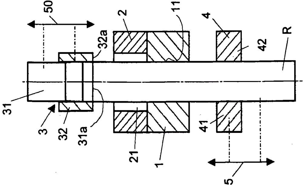
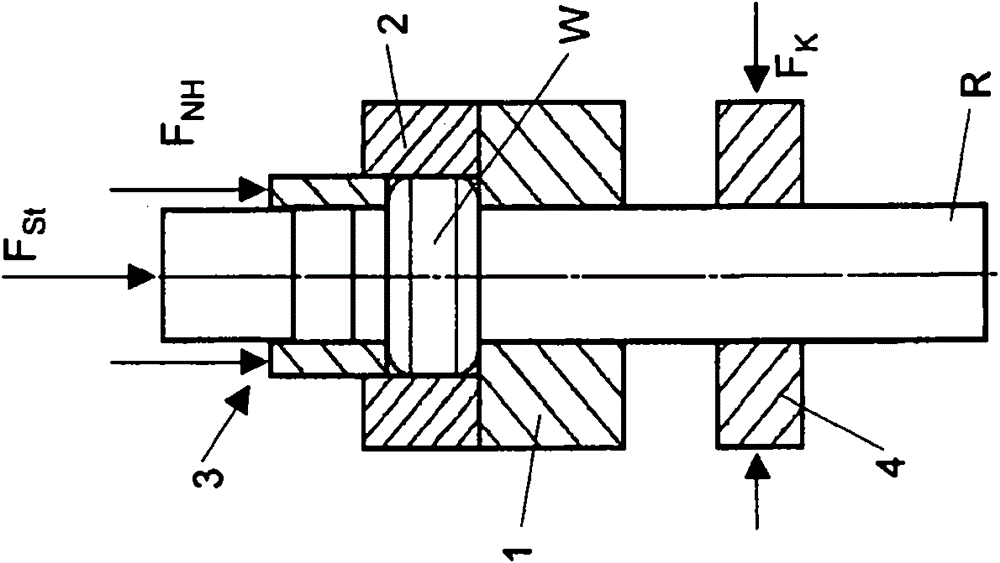
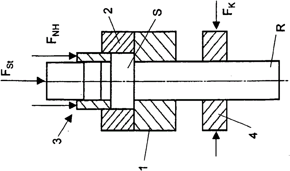
[0029] Figure 1-6 A first embodiment of the invention is described, in which only the essential parts of the device for understanding the invention are shown. A guide 1, a die 2 arranged above it, a die 3 and a clamping device 4 as well as the feed devices 5 and 50, symbolized only by an arrow, can be seen for a Cross-sectional rod-shaped blank R for the clamping device 4 and for the die 3 . The guide 1 , the die 2 , the die 3 and the clamping device 4 are positioned concentrically with one another. The die 3 comprises a punch 31 and a substantially sleeve-shaped or annular hold-down device 32 surrounding the punch. The guide 1 and the die 2 are fixed, while the die 3 and the clamping device 4 are axially movable. The guide device 1, the die 2, the die 3, the clamping device 4 and the feed device 5, 50 are parts o...


PUM


Abstract

To produce a molded part with a through-hole, a rod-shaped blank is pushed through a guide into a cavity and fixed in place. The end region of the blank is compressed and reshaped into a disk. A disk core having the same cross-sectional shape as the blank is ejected out of the disk using a punch and pushed into the guide and moved back together with the unshaped part of the blank. The disk is severed from the disk core and the molded part is removed from the cavity. During the penetration step, the disk present in the cavity is subjected to an axial pressure in the disk core ejection direction and the blank is subjected to an axial counter-force opposite to the disk core ejection direction.

Description

technical field [0001] The invention relates to a method for producing a molded part provided with a through-opening and a device for carrying out the method. Background technique [0002] Such a method is known, for example, from DE 3147897 A1. According to this document, the mass production of the same ring-shaped metal parts is carried out by forming a disc from a metallic, rod-shaped blank by upsetting and the resulting deformation of an end region of the blank and by The disk is then punched axially with a punch having the same cross-sectional shape as the (unupset) blank and the disk core punched out by the punch is separated from the disk. The disc core integral with the unupset blank part forms together with the latter the starting point for another method cycle, until the remaining blank remainder is no longer sufficient for forming further molded parts and is discarded as scrap. [0003] During punching out of the disc core, an unsatisfactory fracture with cracks...

Claims


Application Information

Patent Timeline
Patent Type & Authority Patents(China)
IPC IPC(8): B21K1/04B21K1/76
CPCB21K1/761B21K1/04
Inventor A·马特M·武尔坎
Owner HATEBUR UMFORMMASCHEN
Why Eureka
Try Eureka