Ultrasonic measurement device and ultrasonic measurement method

An ultrasonic and measurement technology, applied in the analysis of solids using sonic/ultrasonic/infrasonic waves, measuring devices, and material analysis using sonic/ultrasonic/infrasonic waves, etc. Resolution and other issues, to achieve the effect of improving the measurement resolution

Active Publication Date: 2011-10-12
JFE STEEL CORP
View PDF5 Cites 5 Cited by
  • Summary
  • Abstract
  • Description
  • Claims
  • Application Information

AI Technical Summary

Problems solved by technology

[0029] This method also has the problem of not being able to improve the resolution when using a highly focused ultrasound beam
Specifically, there are problems in the case of using a focused ultrasonic probe with a large ultrasonic vibrator or an array type ultrasonic probe with a large area of ​​the ultrasonic vibrator array used for aperture synthesis processing, and the focal length, distance to the subject When the conversion distance of the distance and the contact mediu

Method used


Image

  • Ultrasonic measurement device and ultrasonic measurement method
  • Ultrasonic measurement device and ultrasonic measurement method
  • Ultrasonic measurement device and ultrasonic measurement method

Examples


Embodiment approach 1

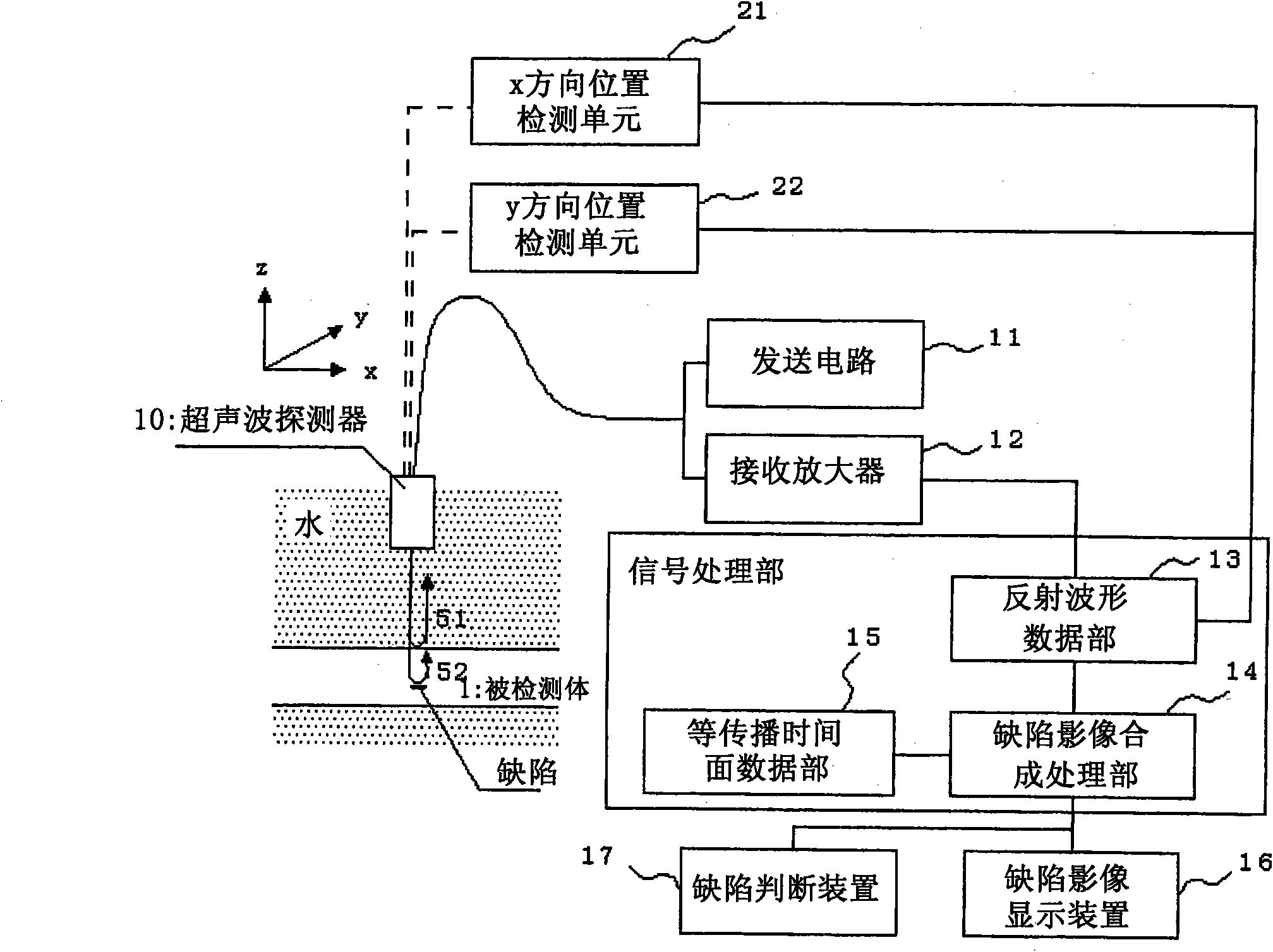
[0099] figure 1 It is a block diagram showing the configuration of an ultrasonic imaging device as an example of the ultrasonic measurement device according to Embodiment 1 of the present invention.

[0100] figure 1 Among them, 1 represents the object to be inspected. In this example, the object 1 is a stationary object, water is used as a medium, and internal defects are imaged using a liquid immersion method. 10 is a focused ultrasonic probe for transmitting and receiving focused beams (hereinafter referred to simply as "ultrasonic probe"), which transmits focused ultrasonic beams towards the subject 1 through electric pulses of a certain period from the transmitting circuit 11, and receives signals from the subject 1. Reflected waves (echoes) from the surface and interior of the body 1. The received signal is amplified by the receiving amplifier 12 to an appropriate level suitable for subsequent signal processing.

[0101]In addition, the transmitting circuit 11 and ...

Embodiment approach 2

[0150] This embodiment 2 is to make figure 1 An example in which the defective image synthesis processing unit 14 performs processing different from the above-mentioned arithmetic processing. The defect image synthesis processing unit 14 of the second embodiment uses delay time data instead of the above-mentioned equal propagation time plane data. Therefore, instead of the isopropagation time plane data unit 15, a storage device (not shown) for storing delay time data is provided. The delay time data (delay time group) is based on the variation data of the propagation time (performing Image 6 The data before the transformation) to find out, such as Figure 13 As shown in the conceptual diagram of , the longer the variation data of the propagation time, the smaller the delay time, and the shorter the variation data, the larger the delay time. Similar to the isopropagation time surface data, each value corresponding to the water distance / defect depth is calculated and store...

Embodiment approach 3

[0161] Figure 14 It is a block diagram showing the configuration of an ultrasonic imaging device, which is an example of the ultrasonic measurement device according to Embodiment 3 of the present invention. Figure 14 Among them, 1 represents the object to be inspected. In this example, the object to be inspected 1 is a static object to be inspected, water is used as a medium, and internal defects are imaged using a liquid immersion method. 10 is an array-type ultrasonic probe for transmitting and receiving ultrasonic waves. The electric pulses of a certain period from the transmitting circuit 111 are sent to each vibrator through the drive element selection circuit 112 to send ultrasonic beams toward the subject 1, and receive signals from the subject 1. Reflected waves (echoes) from the surface and interior of the body 1. The received signal is subjected to aperture synthesis processing by the receiving circuit 113 and the array signal processing circuit 114, and amplifie...


PUM


Abstract

An ultrasonic measurement device comprises a transmitting and receiving means (11, 12) and an aperture synthesis processing means (14). The transmitting and receiving means (11, 12), while allowing a focal point formed by an ultrasonic probe (10) to relatively scan a specimen, transmits an ultrasonic wave toward the specimen and receives a reflected wave from an internal defect of the specimen. The aperture synthesis processing means (14) performs aperture synthesis processing on a signal received at each measurement point using a reference transmission time which is obtained by treating the waveform of the ultrasonic wave transmitting between the ultrasonic probe and the internal defect as an ultrasonic waveform synthesized over the entire surface of a transmission and reception surface.

Description

technical field [0001] The present invention relates to an ultrasonic measuring device and an ultrasonic measuring method, and particularly relates to the use of the ultrasonic flaw detection method, which is a kind of non-destructive inspection method, for inspection of objects of various shapes such as plates, pipes, and cylinders made of metals, resins, etc. Measurement of internal defects existing in the body. Background technique [0002] Conventionally, the ultrasonic flaw detection method, which is a kind of non-destructive inspection method, has been widely used for internal flaw detection of steel materials and the like. In this internal defect detection, in order to obtain more detailed information on internal defects, higher resolution of ultrasonic images is required, and the following conventional technologies exist as methods for higher resolution of ultrasonic images. [0003] (1) C-scan ultrasonic flaw detection method [0004] There is a C-scan ultrasonic ...

Claims


Application Information

Patent Timeline
IPC IPC(8): G01N29/04
CPCG01N29/069G01N29/221G01N2291/044G01N2291/102
Inventor 尾关孝文高田一
Owner JFE STEEL CORP
Why Eureka
Try Eureka