Wireless laser charger

A laser charger, wireless technology, applied in the direction of collectors, optical radiation generators, electric vehicles, etc., can solve the problems of being susceptible to interference, large charging radiation, and entanglement of charger extension wires, and achieves good monochromaticity, Avoid the effect of connecting

Inactive Publication Date: 2011-10-19
CENT TESTING INT GRP CO LTD
View PDF5 Cites 20 Cited by
  • Summary
  • Abstract
  • Description
  • Claims
  • Application Information

AI Technical Summary

Problems solved by technology

As people become more and more dependent on the benefits of these portable electronic devices, it is very important to enable users to use these devices at any time, but the existing chargers for these electronic devices need to be wired. To connect with these electronic devices to be charged, on the one hand, when carrying the charger of the electronic device, the entanglement of the extended wire of the charger brings troubles to people, on the other hand, when charging, the wired connection is also very inconvenient
[0003] Now there is a wireless charger that uses electromagnetic charging technology, but electromagnetic waves are divergent and are more likely to be interfered. Lasers are unidirectional and less susceptible to interference, so they are more conducive to energy concentration; in addition, electromagnetic waves are divergent , its radiation range is larger than that of laser
[0004] The existing chargers have the following disadvantages: 1. The chargers of most electronic devices are wired, and the chargers and electronic devices must be connected by extension wires; 2. The wireless charging method using electromagnetic waves is easily interfered, and Its charging radiation is larger than that of laser

Method used


Image

  • Wireless laser charger
  • Wireless laser charger
  • Wireless laser charger

Examples


Embodiment Construction

[0011] In order to further illustrate the technical means and effects adopted by the present invention to achieve the intended purpose, the present invention will be further described below in conjunction with the accompanying drawings and embodiments.

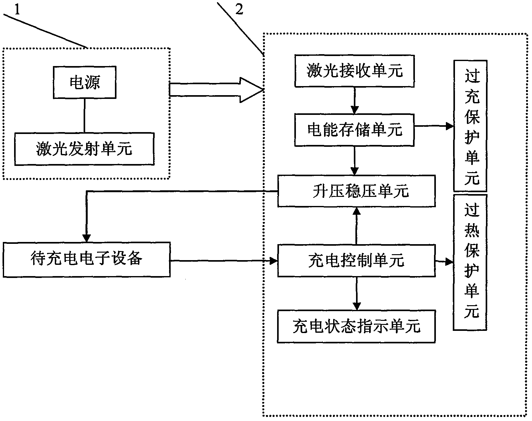
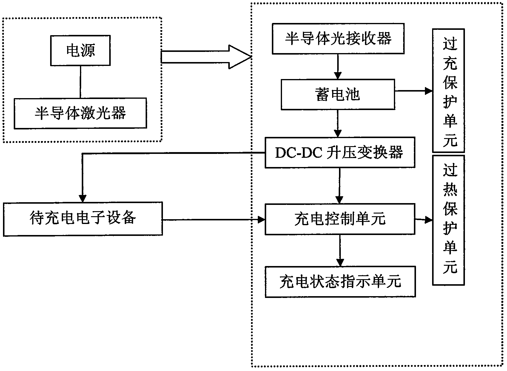
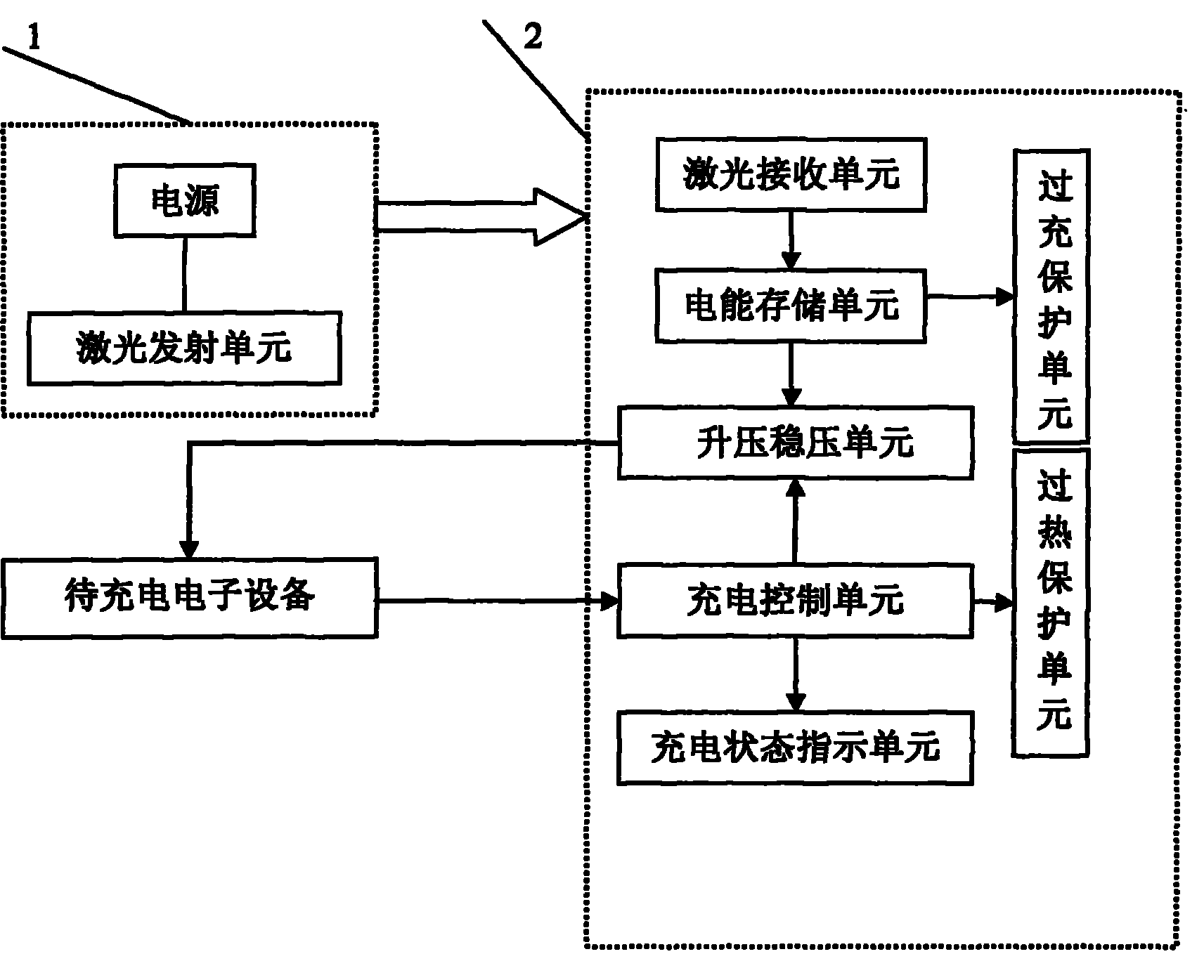
[0012] like figure 1 As shown, the wireless laser charger involved in the present invention includes two parts: a laser emitting end and a laser receiving charging end; the laser emitting end 1 is a laser emitting unit, the input end is connected to a power supply, and the laser receiving and charging end 2 can be integrated in On the electronic device, it can also be a separate module, and then receives the charging electronic device. The specific circuit unit includes: a laser receiving unit, an electric energy storage unit, a voltage boosting and stabilizing circuit, a charging control circuit, a charging state indicating circuit, an overcharging protection circuit and an overheating protection circuit.

[0013] The laser ...


PUM


Abstract

The invention discloses a wireless laser charger that can be widely applied to charge mobile phones, MP3, notebook computers and the like. The wireless laser charger comprises a laser emitting unit, a laser receiving unit, an electric energy storage unit, a boosting and voltage-stabilizing unit and a charging control unit; the laser emitting unit is connected with a power supply; the laser receiving unit is connected with the electric energy storage unit; the electric energy storage unit is connected with the boosting and voltage-stabilizing unit; and the boosting and voltage-stabilizing unit is connected with a charging output terminal that is connected with the charging control unit. In the invention, by designing the circuit that can emit and receive laser and carry out photoelectric conversion and charging control, the wireless laser charger can be realized.

Description

technical field [0001] The invention belongs to the field of optoelectronics, and relates to a wireless laser charger for charging a battery by means of laser. technical background [0002] Portable electronic devices such as cell phones, digital cameras, notebook computers, and various other similar electronic devices provide users with great flexibility and convenience. As people become more and more dependent on the benefits of these portable electronic devices, it is very important to enable users to use these devices at any time, but the existing chargers for these electronic devices need to be wired. To connect with these electronic devices to be charged, on the one hand, when carrying the charger of the electronic device, the entanglement of the extended wire of the charger brings troubles to people; on the other hand, when charging, the wired connection is also very inconvenient. [0003] Now there is a wireless charger that uses electromagnetic charging technology,...

Claims


Application Information

Patent Timeline
Patent Type & Authority Applications(China)
IPC IPC(8): H02J7/00H02N6/00
Inventor 董宁石志娟林劲松李波郭冰郭勇
Owner CENT TESTING INT GRP CO LTD
Why Eureka
Try Eureka