Evaporative vacuum drainer

A liquid drainer and vacuum technology, applied in the field of evaporative vacuum liquid drainer, can solve the problems of no automatic control system, not very suitable, etc.

Inactive Publication Date: 2011-10-26
高翔
View PDF4 Cites 1 Cited by
  • Summary
  • Abstract
  • Description
  • Claims
  • Application Information

AI Technical Summary

Problems solved by technology

However, the small evaporator does not have an automatic control system itself, so it is not very suitable to use a set of automatic control system for vacuum drainage.

Method used


Image

  • Evaporative vacuum drainer
  • Evaporative vacuum drainer
  • Evaporative vacuum drainer

Examples


Embodiment Construction

[0018] The present invention will be further described below with regard to specific embodiments.

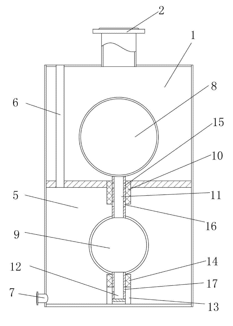
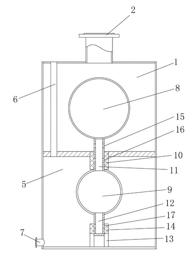
[0019] according to Figure 2-Figure 5 , the present invention comprises a vacuum chamber 1, a balance chamber 5, a hollow floating device mainly composed of an upper float 8, a lower float 9, a sliding pipe 11, and a drainage pipe 12, a vacuum valve group, and a balance valve group.

[0020] The vacuum valve group is composed of a water hole a15 and a hole valve switch. The water hole a15 is located on the sliding pipe 11 at the connection between the sliding pipe 11 and the upper floating ball 8. The a hole valve switch is located outside the water hole a15 or on the On or formed by the sealed channel 10, the sealed channel 10 is used as the a hole valve switch of the water hole a15 in the figure.

[0021] The balance valve group is composed of water hole b16, water hole c17, b-hole valve switch, and c-hole valve switch. Below a15; the water hole c17 is located on the draina...


PUM


Abstract

The invention relates to an evaporative vacuum drainer, which comprises a vacuum chamber, a balance chamber, a hollow sink-and-float device, a vacuum valve set and a balance valve set, wherein an evaporator heating chamber connector is formed on the vacuum chamber; the balance chamber is positioned under the vacuum chamber; an air inlet pipe and a water outlet are arranged on the balance chamber;the upper half part of the sink-and-float device is positioned in the vacuum chamber; the lower half part of the sink-and-float device is positioned in the balance chamber; the vacuum valve set is arranged at the upper half part of the sink-and-float device; the balance valve set is arranged at the lower half part of the sink-and-float device; when the sink-and-float device floats upwards, the vacuum valve set is opened and the balance valve set is closed; and when the sink-and-float device sinks, the vacuum valve set is closed and the balance valve set is opened. The evaporative vacuum drainer has the advantages that the evaporated condensate water can be drained out of a system at vacuum state without the help of an external energy resource.

Description

technical field [0001] The invention relates to an evaporation device, in particular to an evaporation vacuum drainer. Background technique [0002] In order to reduce energy consumption and reduce pollution, many evaporating and concentrating devices that used to be boiled in large pots have been changed into multi-effect evaporating devices. [0003] In the multi-effect evaporator, the shell side of the last effect heating chamber is often in a negative pressure state. Therefore, in order to discharge steam condensed water, foreign methods are currently used in China to pump the condensed water with a vacuum pump 18, such as figure 1 . In foreign countries, the amount of water pumped is automatically controlled by the instrument. Domestic manufacturers basically do not use automatic control devices, resulting in either excessive suction and steam being taken away as water, resulting in increased steam consumption, or insufficient suction and drainage, resulting in water ...

Claims


Application Information

Patent Timeline
Patent Type & Authority Applications(China)
IPC IPC(8): B01D1/30B01D1/26
Inventor 顾仲良吴顺高翔
Owner 高翔
Why Eureka
Try Eureka