Multistation automatic pipe cutting machine

A multi-station, pipe cutting machine technology, applied in the direction of pipe shearing device, shearing device, manufacturing tools, etc., can solve the problems of wasting time and reducing production efficiency, so as to improve the dimensional accuracy of finished products, improve production efficiency, and ensure the surface Effects of Finish and Squareness

Inactive Publication Date: 2011-10-26
赵建华
View PDF4 Cites 18 Cited by
  • Summary
  • Abstract
  • Description
  • Claims
  • Application Information

AI Technical Summary

Problems solved by technology

[0003] Since these pipe cutting machines all have a cutting position, and the center point of the saw blade of the cutting device cuts the pipe reciprocatingly with a straight line or an arc as the movement track, both cutting and feeding must wait for each other, and the result is Waste of time and reduce productivity

Method used


Image

  • Multistation automatic pipe cutting machine
  • Multistation automatic pipe cutting machine
  • Multistation automatic pipe cutting machine

Examples


Embodiment 1

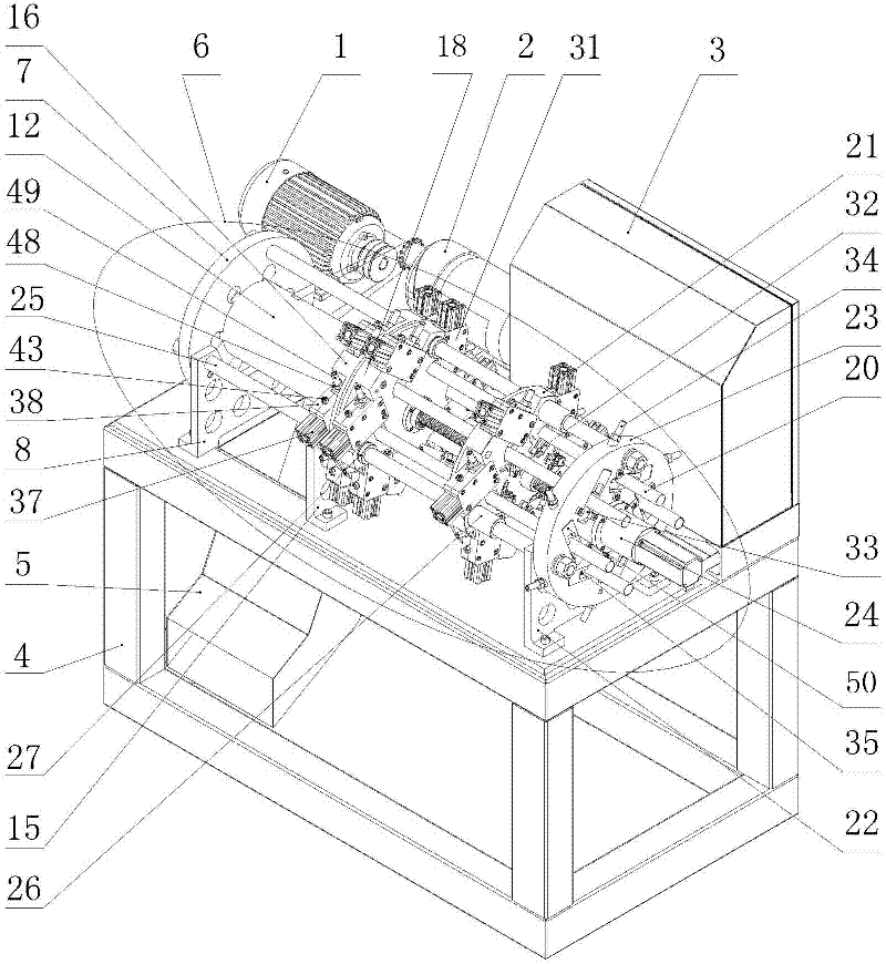
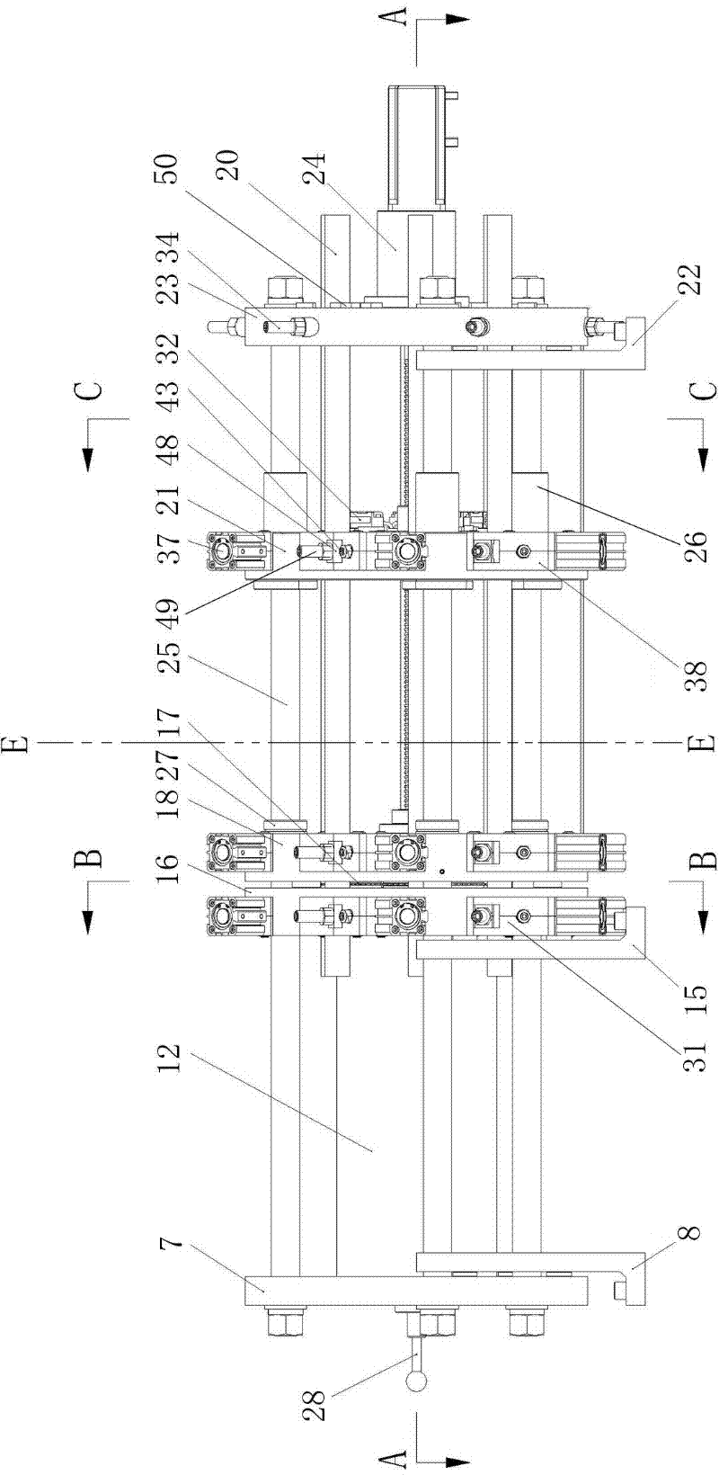
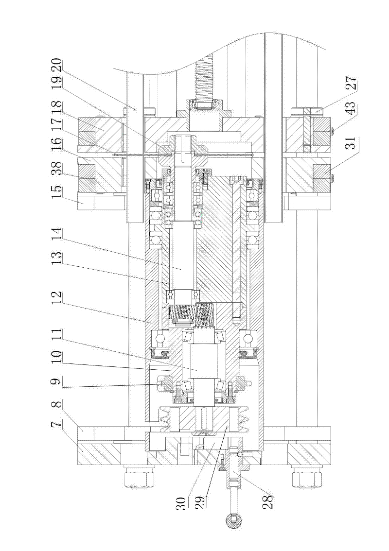
[0029] Such as figure 1- As shown in -10, the multi-station automatic pipe cutting machine includes a frame 4, a motor 1, a reducer 2 located at the matching position of the frame 4, and a mechanism for controlling the automatic coordination of each part of the machine according to a predetermined program. The electrical control box 3 is provided with a main mechanism 6 controlled by the electrical control box 3 on the top of the frame 4, and is used for carrying cutting, clamping, and feeding; 6. Three connecting plates 8, 15, 22 are used to fix on the frame 4. The main body mechanism 6 and the three connecting plates 8, 15, 22 are respectively provided with a main body fixing plate 7, a middle main body fixing plate 16 and a The fixed plate 23; the connecting plates 8, 15, 22 are connected with the main body fixed plate 7, the middle main body fixed plate 16 and the fixed plate 23 through three guide rail shafts 25 in the axial direction, and the fitting position between the...

Embodiment 2

[0033] The feeding driving device 24 is composed of a cylinder or an oil cylinder, that is, the cylinder or the oil cylinder body is fixed on the fixed plate 23, and the piston rod is connected with the feeding clamping fixed plate 21 as the power output end of the feeding driving device 24, and the others are the same as in Embodiment 1. No longer.

[0034] Specifically use the working process of the present invention: first connect the power supply and the gas source, adjust the pressure of the gas source, turn on the power switch and the reset switch on the electrical control box 3, the feeding drive device 24 drives the feeding clamping device fixing plate 21, and the The pipe material 20 clamped by the clamps 31 corresponding to the positions of a and b material holes is sent into the material hole of the corresponding processing position of the middle main body fixing plate 16 and the cutting and clamping fixing plate 18, and the clamps 31 at the corresponding positions c...


PUM


Abstract

The invention relates to pipe cutting equipment and in particular relates to an efficient multistation automatic pipe cutting machine which can be used for simultaneously carrying out cutting and charging. The multistation automatic pipe cutting machine is characterized in that a positioning sleeve having the same central line with a main body fixing plate and a middle main body fixing plate is arranged between the main body fixing plate and the middle main body fixing plate; a belt pulley which is connected with a motor by virtue of a belt is arranged at one end of an input shaft having the same central line with the positioning sleeve; the other end of the input shaft is connected with one end of a main shaft by virtue of gears mutually meshed, and a saw blade is arranged at the other end of a main shaft; the saw blade is positioned between the middle main body fixing plate and the cutting and clamping fixing plate, and connected with the main shaft by virtue of a locking cover, anda front rotating body and a rear rotating body are respectively sheathed on the input shaft and the main shaft which are positioned at adjacent sides of the belt pulley by virtue of bearings; the front rotating body and the rear rotating body are connected by virtue of bolts, and a chain wheel is arranged on an adaptive position of the front rotating body; and the chain wheel is connected with a chain wheel arranged on a speed reducer by virtue of a chain, and a feeding driving device is arranged on the fixing plate, and the power output end of the feeding driving device is connected with a feeding and clamping fixing plate.

Description

technical field [0001] The invention relates to a pipe cutting device, in particular to a high-efficiency multi-station automatic pipe cutting machine capable of simultaneous cutting and feeding. Background technique [0002] At present, most automatic pipe cutting machines clamp the pipe through the feeding device and send it to the cutting position with a preset length, then the pipe is clamped by the clamping device at the cutting position, and the cutting device in the waiting state starts cutting after clamping At the same time, the feeding device releases the pipe, returns to the original position and clamps the pipe again, waits for the cutting device to finish cutting and returns to the original position, after the clamping device at the cutting position releases the pipe, the feeding device sends the pipe to the cutting position again for clamping , cutting, and complete a working cycle. [0003] Since these pipe cutting machines all have a cutting position, and th...

Claims


Application Information

Patent Timeline
IPC IPC(8): B23D47/00B23D47/04B23D47/08B23D21/00
Inventor 赵建华
Owner 赵建华
Why Eureka
Try Eureka