
Testing device for deep wells and high-temperature and high-pressure wells

A high temperature and high pressure, testing device technology, applied in wellbore/well valve devices, isolation devices, wellbore/well components, etc. The effect of eye collapse, stable liquid and gas flow rate, and convenient use

Inactive Publication Date: 2013-11-13
BC P INC CHINA NAT PETROLEUM CORP +1
View PDF2 Cites 0 Cited by
  • Summary
  • Abstract
  • Description
  • Claims
  • Application Information

AI Technical Summary

Problems solved by technology

[0003] The present invention provides a testing device for deep wells and high-temperature and high-pressure wells, which overcomes the deficiencies of the prior art, and can effectively solve the problem that conventional ground testing devices cannot meet the technical requirements of stably controlling the high-speed liquid flow rate during the test mining and testing process. The problem

Method used


Image

  • Testing device for deep wells and high-temperature and high-pressure wells
  • Testing device for deep wells and high-temperature and high-pressure wells
  • Testing device for deep wells and high-temperature and high-pressure wells

Examples


Embodiment Construction

[0040] The present invention is not limited by the following examples, and specific implementation methods can be determined according to the technical solutions of the present invention and actual conditions.

[0041] In the present invention, for the convenience of description, the description of the relative positional relationship of each component is based on the description attached to the description. figure 1 For example, the positional relationship of top, bottom, left, right, etc. is determined according to the layout direction of the drawings in the specification.

[0042] Below in conjunction with embodiment and accompanying drawing, the present invention will be further described:

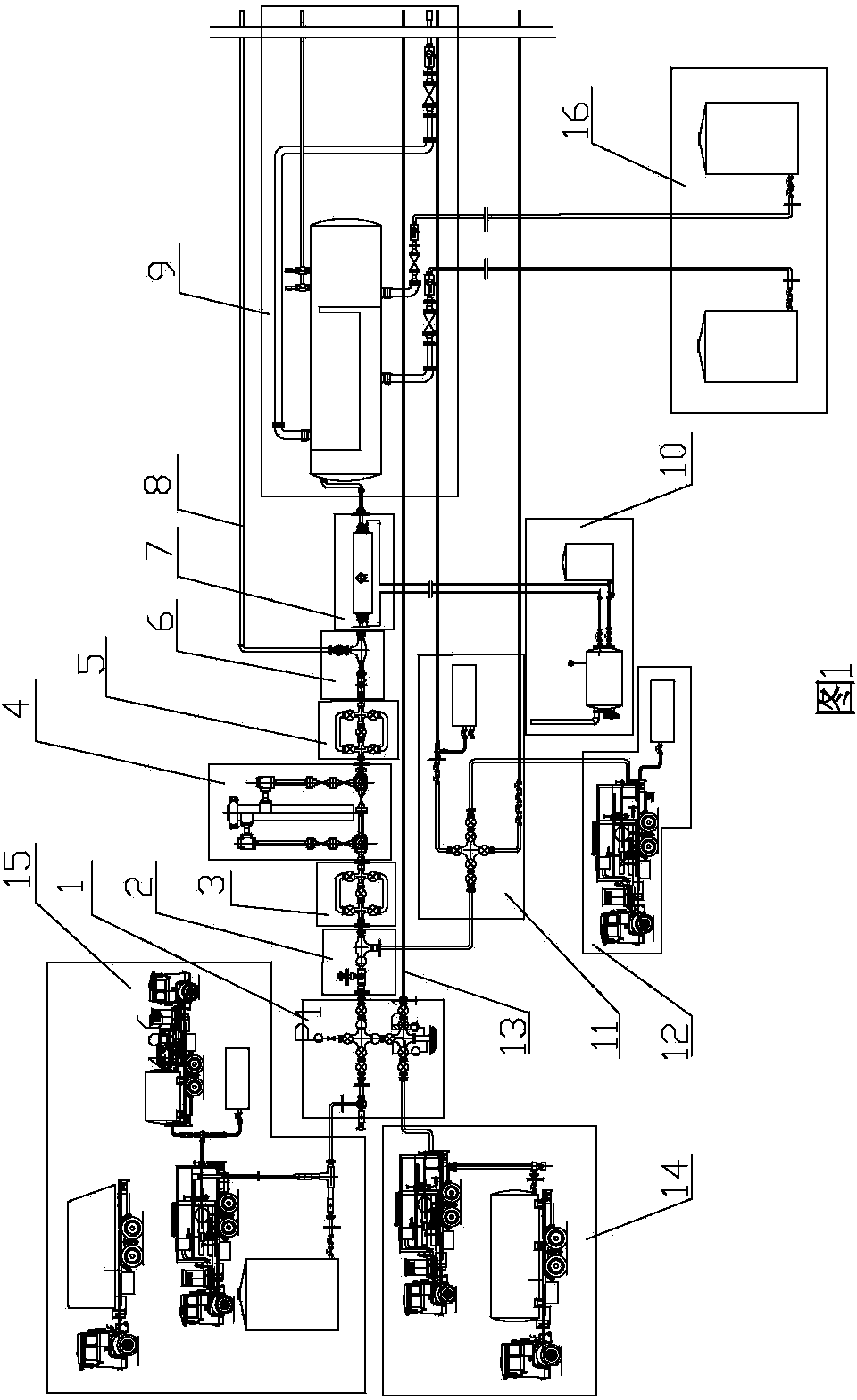
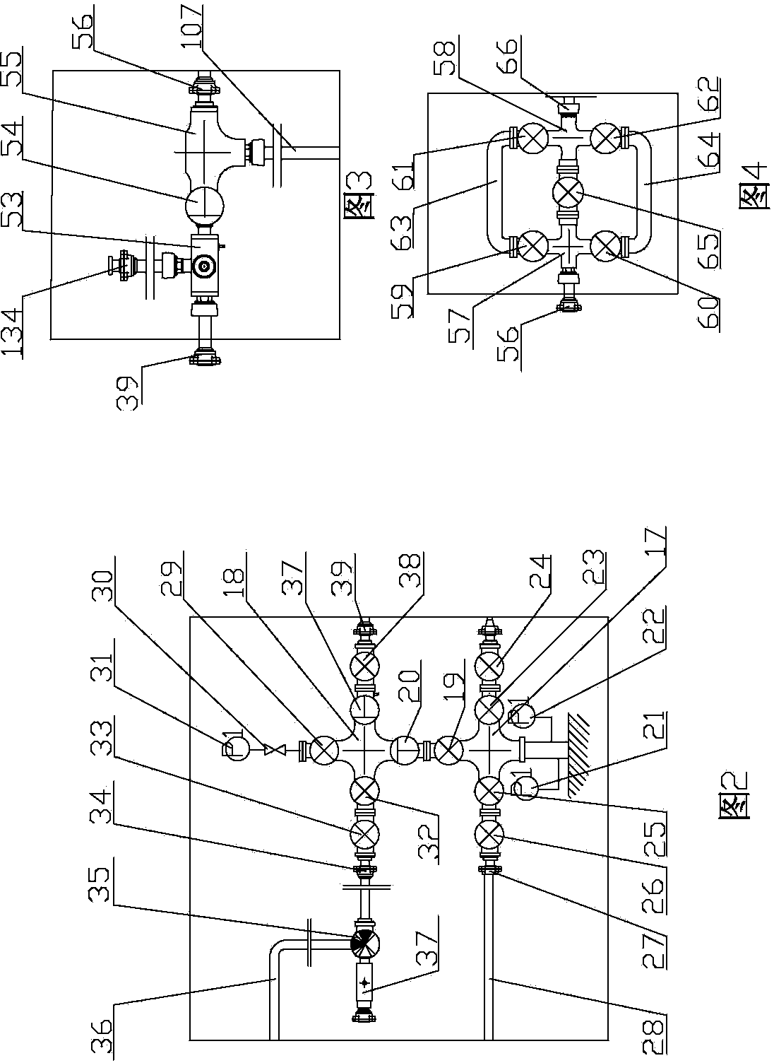
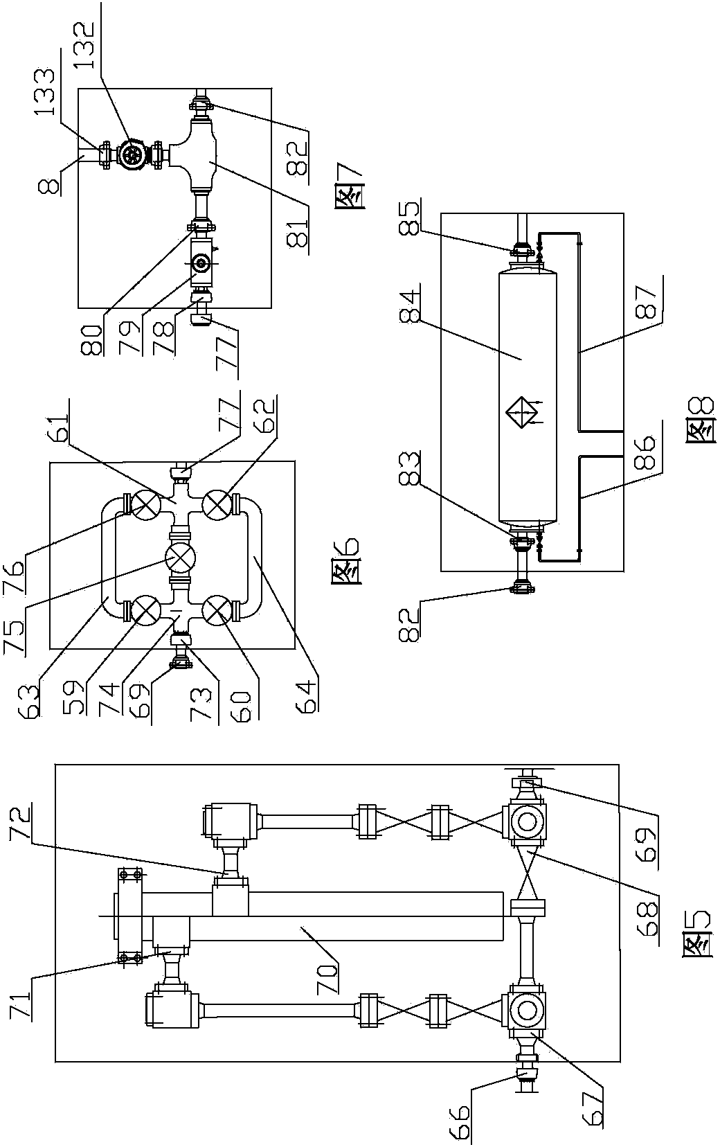
[0043] as attached figure 1 As shown, the deep well and high temperature and high pressure well testing device includes a gas production wellhead 1, an injection device 2, a front nozzle manifold 3, a desander 4, a rear nozzle manifold 5, an emergency vent valve 6, a heat exchanger 7,...


PUM


Abstract

The invention relates to the technical field of oil well testing devices and in particular relates to a testing device for deep wells and high-temperature and high-pressure wells. The testing device comprises a gas production wellhead, an injection device, a front oil nozzle manifold, a desander, a rear oil nozzle manifold, an emergency blowout prevention valve, a heat exchanger, a blowout prevention pipe, a high-pressure three-phase separator, a heat supply device, a sleeve blowout prevention pipe, a sleeve fracturing truck unit, a jet hole, a fracturing truck unit, oil and a water tank group; the gas production wellhead is connected with the jet hole, the fracturing truck unit, the sleeve fracturing truck unit, the injection device and the sleeve blowout prevention pipe together respectively; the injection device, the front oil nozzle manifold, the desander, the rear oil nozzle manifold, the emergency blowout prevention valve, the heat exchanger and the high-pressure three-phase separator are sequentially connected together; and the upper end of the emergency blowout prevention valve is fixedly connected with the blowout prevention pipe together. The device provided by the invention has the advantages that the structure is reasonable and compact, the use is convenient, the pressure of the formation can be effectively maintained, the collapse of a borehole can be avoided, the sand production rate can be reduced, the liquid-gas flow rate can be smoothly controlled, the desanding can be performed timely, and oil testing and oil production work can be further performed safely.

Description

technical field [0001] The invention relates to the technical field of oil well testing devices, and relates to a testing device for deep wells and high-temperature and high-pressure wells. Background technique [0002] In the testing process of deep wells and high-temperature and high-pressure oil and gas wells, there are the following characteristics: 1. The formation pressure coefficient is higher than 2.0; 2. The reservoir is buried deep and the formation temperature is high; Hole collapse, wellbore quality is not good, the formation is prone to sand production during the oil testing process, and the sand production pressure difference is small; 4. There is a large amount of killing fluid leakage in the fractured formation during drilling, which limits fluid drainage and production; 5. The wellbore structure adopts small casing for liner and special thick-walled casing completion method, which requires complex test production process; the conventional surface test device...

Claims


Application Information

Patent Timeline
Patent Type & Authority Patents(China)
IPC IPC(8): E21B43/22E21B43/26E21B43/12E21B43/02E21B43/34E21B34/02E21B36/00
Inventor 周正炳邱露
Owner BC P INC CHINA NAT PETROLEUM CORP
Learn More