
Refrigerator

A refrigerator and box body technology, applied in the field of refrigerators, can solve the problems of large energy loss, short storage time, energy loss, etc., and achieve the effects of improving refrigeration efficiency, improving storage time, and reducing energy loss.

Active Publication Date: 2011-10-26
HEFEI MIDEA REFRIGERATOR CO LTD +1
View PDF7 Cites 4 Cited by
  • Summary
  • Abstract
  • Description
  • Claims
  • Application Information

AI Technical Summary

Problems solved by technology

[0002] Existing refrigerators with automatic ice-making function are all single-system refrigerators, that is, the refrigeration system has only one evaporator, and the evaporator is located in the freezer compartment. The cold air is conveyed from the freezer to the refrigerator or ice-making room through the fan and the air duct. The air duct has a long stroke and the air flow resistance is relatively large, so the energy loss is relatively large.
[0003] In addition, due to the structural characteristics of the single refrigeration system, the cold air circulates between the freezer, ice-making room, and refrigerating room, and the moisture in the refrigerating room will be lost to the freezing room, ice-making room, etc. Humidity is difficult to maintain, so the air-drying phenomenon of this type of refrigerator on the market is more prominent at present, and foods with high water content such as vegetables and fruits have a shorter storage time
[0004] In addition, for the refrigerator that the automatic ice maker is arranged in the freezer and cannot take ice from the outside of the casing, it is necessary to open the door of the freezer and then take the ice when ice is needed, and because the existing refrigerator usually The freezer is located at the lower part of the refrigerator, and the user needs to bend over when taking ice, causing a lot of inconvenience, which is not conducive to the preservation of cold air in the freezer, and is prone to unnecessary energy loss

Method used


Image

  • Refrigerator
  • Refrigerator
  • Refrigerator

Examples


Embodiment Construction

[0027] Embodiments of the present invention are described in detail below, examples of which are shown in the drawings, wherein the same or similar reference numerals designate the same or similar elements or elements having the same or similar functions throughout. The embodiments described below by referring to the figures are exemplary only for explaining the present invention and should not be construed as limiting the present invention.

[0028] In describing the present invention, it should be understood that the terms "center", "longitudinal", "transverse", "upper", "lower", "front", "rear", "left", "right", " The orientations or positional relationships indicated by "vertical", "horizontal", "top", "bottom", "inner", "outer", etc. are based on the orientation or positional relationships shown in the drawings, and are only for the convenience of describing the present invention and simplifying Describes, but does not indicate or imply that the device or element referred...


PUM


Abstract

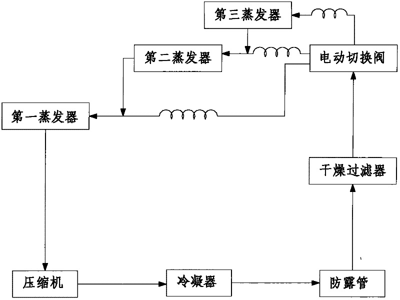
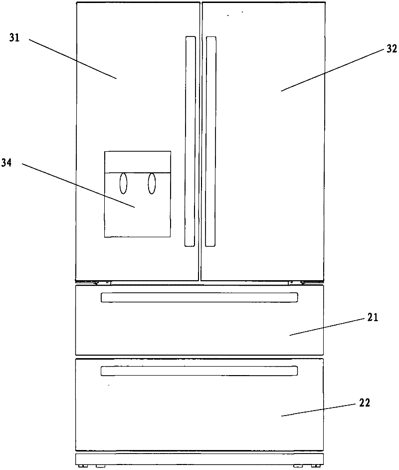
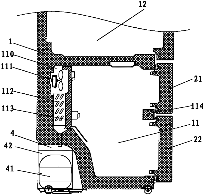
The invention discloses a refrigerator. The refrigerator comprises a body, freezing chamber door bodies, refrigerating chamber door bodies, an ice maker and a refrigerating system, wherein a freezing chamber and a refrigerating chamber arranged above the freezing chamber are formed in the body; an ice making chamber is arranged on the inner wall of one refrigerating chamber door body and an ice getting groove connected with the ice making chamber is arranged on the outer surface of the refrigerating chamber door body; the ice maker is arranged in the ice making chamber; the refrigerating system comprises a compressor, a condenser, a first evaporator, a second evaporator, a third evaporator and an electric changeover valve; the compressor and the condenser are arranged in a compressor cabin arranged on the lower part of the rear side of the body; the first evaporator is arranged in the freezing chamber and is used for refrigerating the freezing chamber; the second evaporator is arranged in the refrigerating chamber and is used for refrigerating the refrigerating chamber; the third evaporator is arranged in the ice making chamber and is used for refrigerating the ice making chamber;the electric changeover valve is connected with the three evaporators; and the three evaporators adopt the bypass type control mode. The refrigerator disclosed by the embodiment of the invention has the advantages of good moisturizing effect, convenience in use, high refrigerating efficiency and low energy consumption.

Description

technical field [0001] The invention relates to the technical field of refrigeration, in particular to a refrigerator. Background technique [0002] Existing refrigerators with automatic ice-making function are all single-system refrigerators, that is, the refrigeration system has only one evaporator, and the evaporator is located in the freezer compartment. The cold air is conveyed from the freezer to the refrigerator or ice-making room through the fan and the air duct. The air duct has a long stroke and the air flow resistance is relatively large, so the energy loss is relatively large. [0003] In addition, due to the structural characteristics of the single refrigeration system, the cold air circulates between the freezer, ice-making room, and refrigerating room, and the moisture in the refrigerating room will be lost to the freezing room, ice-making room, etc. Humidity is difficult to maintain, so the air-drying phenomenon of this type of refrigerator on the market is ...

Claims


Application Information

Patent Timeline
IPC IPC(8): F25D11/02F25D23/02F25D23/12F25D17/04F25D19/00
CPCF25D17/065F25D2317/062F25D2317/061
Inventor 李凌云程建任伟刘东现王成红
Owner HEFEI MIDEA REFRIGERATOR CO LTD
Learn More