Method for measuring coaxial error of thru-beams
A measurement method and beam technology, applied in the field of optical systems, can solve problems such as large residual angle error, difficult judgment, and inability to meet precision requirements
- Summary
- Abstract
- Description
- Claims
- Application Information
AI Technical Summary
Problems solved by technology
Method used
Image

Examples
Embodiment 2
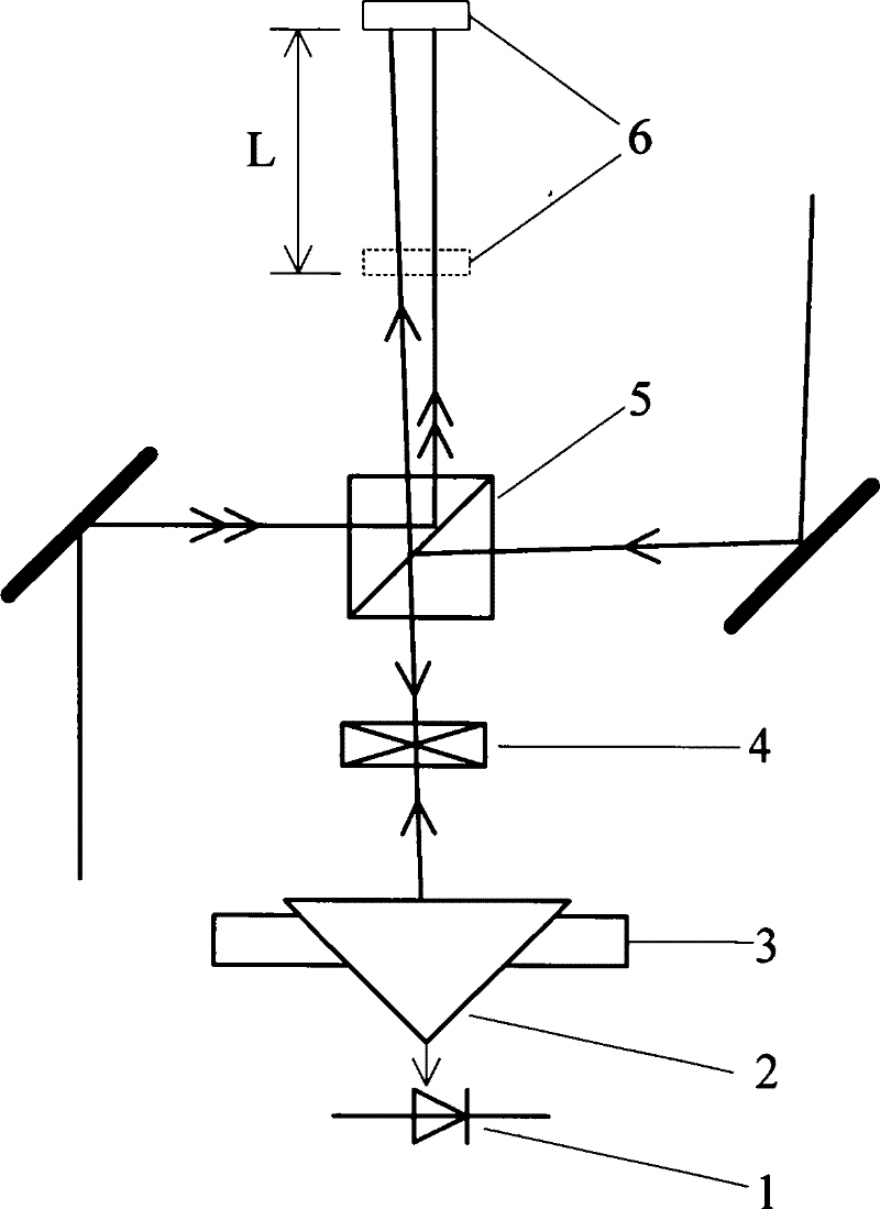
[0041] In embodiment 2, for non-polarized light, the measurement optical path is simpler, only need to change the polarizing beam splitting prism into a beam splitting prism, and remove the quarter wave plate at the same time.
[0042] The method for measuring the coaxial error of the beam of light includes the following steps:
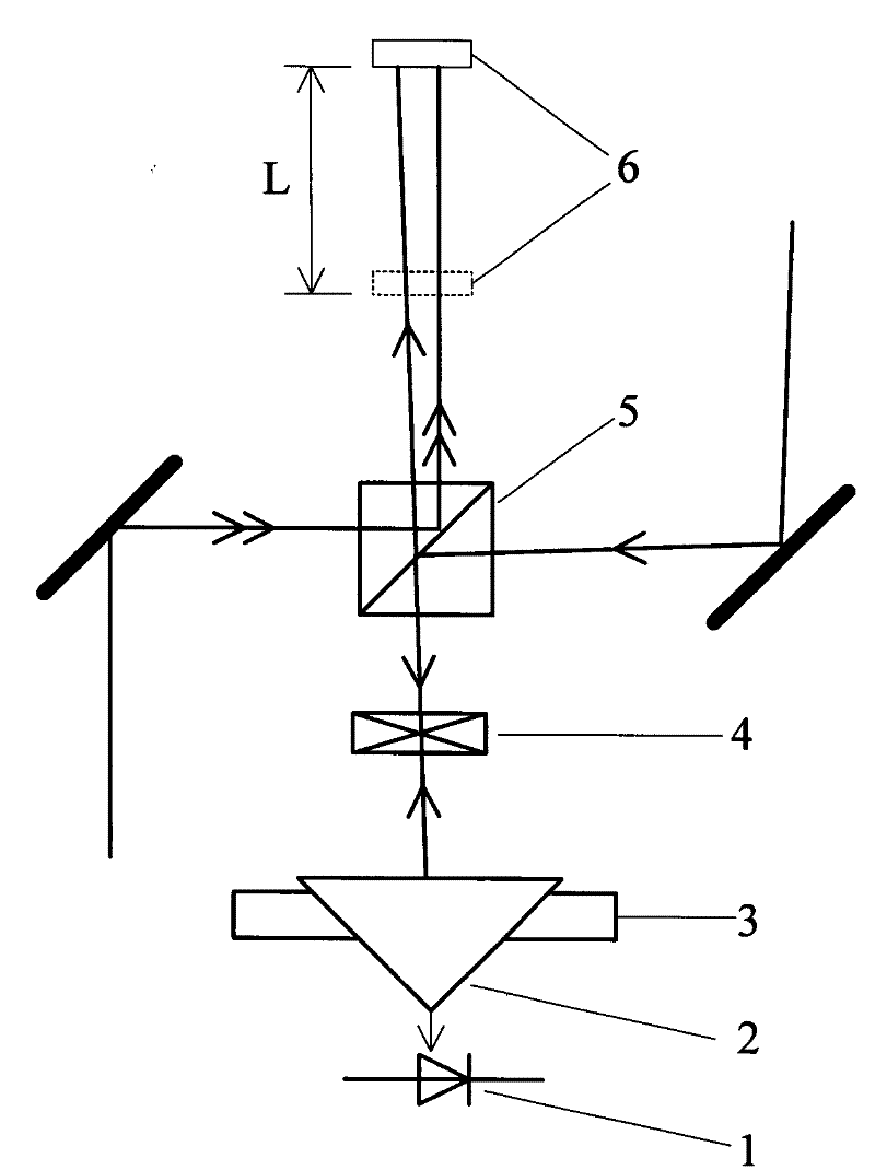
[0043] 1. The two pairs of beams to be measured are respectively called the first beam and the second beam, and a beam splitting prism 5 is inserted in the optical path of the two pairs of beams, so that the beam splitting surface of the beam splitting prism 5 and the The beam is at 45°;
[0044] ②In the direction of the reflected light of the second light beam of the beam splitting prism 5, a corner reflector 2 and a light intensity detector 1 are arranged in sequence, the corner reflector 2 is placed on the two-dimensional translation adjustment frame 3 and the corner reflector 2 The hypotenuse is perpendicular to the reflected light beam, and the ...
PUM
 Abstract
Description
Claims
Application Information
 - R&D
- Intellectual Property
- Life Sciences
- Materials
- Tech Scout
- Unparalleled Data Quality
- Higher Quality Content
- 60% Fewer Hallucinations
Browse by: Latest US Patents, China's latest patents, Technical Efficacy Thesaurus, Application Domain, Technology Topic, Popular Technical Reports.
© 2025 PatSnap. All rights reserved.Legal|Privacy policy|Modern Slavery Act Transparency Statement|Sitemap|About US| Contact US: help@patsnap.com