Micro-lubricating system

A technology of micro-lubrication and flow control valve, which is applied in the direction of engine lubrication, maintenance, safety accessories, mechanical equipment, etc., can solve problems such as low cost, achieve low cost, convenient operation, and solve the effect of large amount of cutting fluid

Active Publication Date: 2011-11-02
BEIHANG UNIV
View PDF8 Cites 15 Cited by
  • Summary
  • Abstract
  • Description
  • Claims
  • Application Information

AI Technical Summary

Problems solved by technology

Inexpensive and more e

Method used


Image

  • Micro-lubricating system
  • Micro-lubricating system
  • Micro-lubricating system

Examples


Embodiment Construction

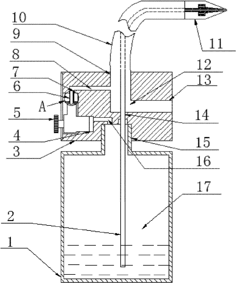
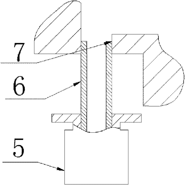
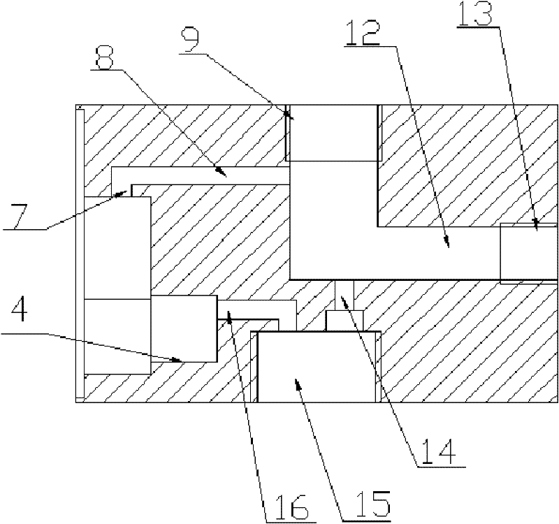
[0028] A minimal quantity lubrication system of the present invention, please refer to figure 1 , figure 2 , image 3 , Figure 4 , including a fuel tank 1, a liquid introduction pipe 2, an upper cover 3, a flow regulating valve 5, an air-introduction thin tube 6, an air outlet pipe 10, and a nozzle 11; the fuel tank 1 and the fuel tank interface 15 of the upper cover are connected by threads to form a hollow closed fuel tank Chamber 17; the upper cover is provided with three chambers, which are the first chamber 12, the second chamber 8 and the third chamber 16; the two ends of the first chamber are the outlet pipe interface 9 and the compressed gas inlet 13 , the second chamber 8 communicates with the third chamber 16 through the flow regulating valve 5; one end of the outlet pipe 10 is connected with the outlet pipe interface 9 of the upper cover, and the other end is connected with the nozzle 11, the nozzle 11 is an inner and outer layer nozzle structure, and the inner ...


PUM


Abstract

The invention relates to a micro-lubricating system which comprises an oil tank, a liquid guide pipe, an upper cover, a flow adjusting valve port, a flow adjusting valve, a gas guide tubule, a gas guide tubule port, a second chamber, a gas outlet port, a gas outlet, a nozzle, a first chamber, a compressed air inlet, a liquid guide through hole, an oil tank port, a third chamber and an oil tank chamber and is characterized in that the oil tank is filled with lubricating agent; the lubricating agent enters a pipeline under the action of compressed gas, and the using amount of the lubricating agent can be adjusted by the adjusting valve; the pipelines are of an internal and external double-layered pipe structure; and the nozzle is of a double-layered spraying structure. The micro-lubricatingsystem can be used as a lubricating agent supply device in micro-lubricating, low-temperature cutting and liquid nitrogen cooling and processing and can be used for reasonably adjusting the using amount of the lubricating agent. The micro-lubricating system has the advantages of simpleness in manufacture, low cost and less consumed resources and can be suitable for batch production. The micro-lubricating system disclosed by the invention solves the problems of large using amount of cutting liquid, control difficulty, serious environment pollution, and the like in the traditional liquid supplysystem by using the non-polluted environment-friendly lubricating agent.

Description

technical field [0001] The invention relates to a micro-quantity lubrication system, in particular to a micro-quantity lubrication device that delivers cutting lubricant to a nozzle for atomization and sprays it to a cutting area at a relatively high speed to lubricate and cool the cutting area. The utility model relates to a coolant supply device belonging to the field of mechanical processing. Background technique [0002] In the process of mechanical processing, the disadvantages of traditional pouring cooling methods are becoming more and more obvious: from the perspective of environmental pollution and health, on the one hand, waste cutting fluid is an important source of pollution to soil and air; on the other hand, the chemical substances contained in cutting fluid will affect workers Cause harm and easily cause various diseases; from the perspective of use cost, on the one hand, the purchase, storage and post-processing of cutting fluid are expensive, on the other ha...

Claims


Application Information

Patent Timeline
IPC IPC(8): B23Q11/12F16N7/32
Inventor 袁松梅刘思严鲁涛刘强
Owner BEIHANG UNIV
Why Eureka
Try Eureka