Automatic electricity-getting mechanism and automatic electricity-getting method for gantry crane
A gantry crane, electric method technology, applied in the direction of transportation and packaging, load hanging components, etc., can solve the problems of low efficiency, low safety, risk of electric shock, etc., and achieve the effect of improving mobility, simple operation, and reducing quantity
- Summary
- Abstract
- Description
- Claims
- Application Information
AI Technical Summary
Problems solved by technology
Method used
Image

Examples
Embodiment 1
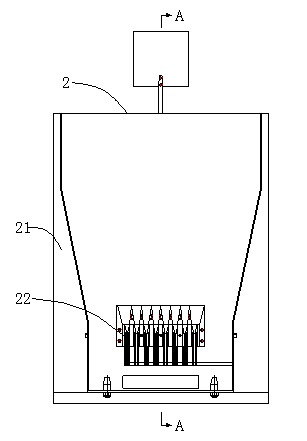
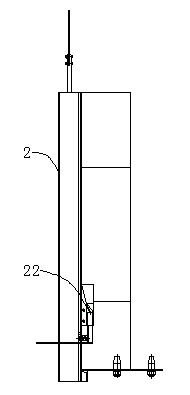
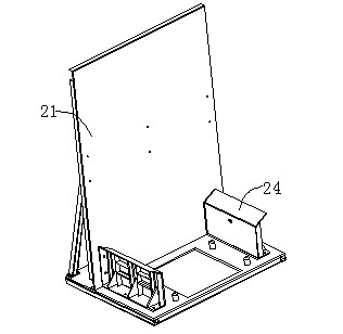
[0037] Embodiment 1. The automatic power-taking mechanism used for gantry cranes in this embodiment includes a connection mechanism. The connection mechanism is connected to a plug frame 1 through a detachable coupling mechanism. The plug frame 1 is matched with a socket frame 2, and the plug frame 1 It can be fixed with the socket frame 2 by a locking mechanism.
[0038] The plug frame 1 includes a plug frame 11 , a coupling assembly 12 for connecting a docking mechanism, a power-taking electrode 13 fixed in the plug frame 11 , and a power cable connected to the power-taking electrode 13 .
[0039] The docking mechanism includes front and rear telescopic modules, up and down moving modules and a detachable coupling assembly 12 connected with the plug frame 1 . Front and rear telescopic modules, moving the modules up and down can make the connecting mechanism control the flexible movement of the plug frame 1. The connection mechanism can be various mechanical arms or mechanic...
Embodiment 2
[0049] Embodiment 2, this embodiment has made further improvement on the basis of embodiment 1.
[0050] In the above step 1, the gantry crane carrying the plug frame 1 is driven to the side of the socket frame 2 with its own power supply. The connecting part of the docking mechanism is connected with the coupling assembly 12 on the plug frame 1 . A cable reel is provided on the gantry crane, and after the connecting mechanism is aligned with the socket frame 2, it pauses first, and then the cable reel works to loosen the power cables connected by the connecting mechanism.
[0051] In this embodiment, the positioning can be done by means of ground marking lines or GPS positioning systems or radio frequency positioning systems or by means of the reflective plate installed on the socket frame 2 and the photoelectric light on the gantry crane or by means of the upper limit stopper installed on the socket frame 2 and the installation After the stroke switch on the gantry crane re...
Embodiment 3
[0060] Embodiment 3, this embodiment has made further improvements to Embodiment 1 or Embodiment 2.
[0061] In this embodiment, in view of the large inertia of the gantry crane, it is difficult for the connecting mechanism to achieve the millimeter-level precise positioning required by the locking mechanism in one step, regardless of whether it relies on GPS, radio frequency positioning system, marking line, or travel switch photoelectric switch when stopping. This is especially true for rubber-tyred gantry cranes and has therefore been further optimized.
[0062] In this embodiment, the ground marking line or the GPS positioning system or the radio frequency positioning system or the photoelectric switching on the reflector installed on the socket frame 2 and the gantry crane or the upper limit stopper installed on the socket frame 2 and the gantry crane are installed. Itinerary consecration has achieved preliminary positioning at the decimeter level. After the preliminary ...
PUM
 Abstract
Description
Claims
Application Information
 - R&D
- Intellectual Property
- Life Sciences
- Materials
- Tech Scout
- Unparalleled Data Quality
- Higher Quality Content
- 60% Fewer Hallucinations
Browse by: Latest US Patents, China's latest patents, Technical Efficacy Thesaurus, Application Domain, Technology Topic, Popular Technical Reports.
© 2025 PatSnap. All rights reserved.Legal|Privacy policy|Modern Slavery Act Transparency Statement|Sitemap|About US| Contact US: help@patsnap.com