

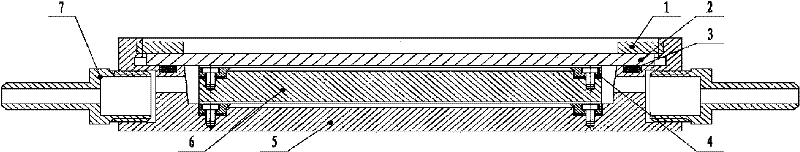
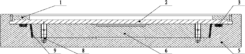
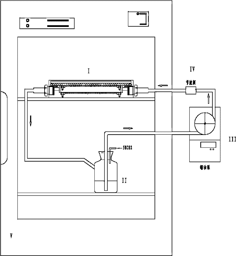
In vitro cell co-culturing double flow mechanical force loaded flow chamber apparatus
A flow chamber and co-cultivation technology, applied in the field of biomechanical engineering research, can solve the problems that two kinds of cells cannot be loaded at the same time, the device cannot be functionally expanded, and the flow rate of the bottom layer of cell culture is slow, so as to simplify the flow chamber installation steps, Good accuracy and small boundary effects
- Summary
- Abstract
- Description
- Claims
- Application Information
AI Technical Summary
Problems solved by technology
Method used
Image

Examples
Embodiment 1
[0025] In the parallel plate flow chamber, the relationship between shear force, circulating fluid flow rate, circulating fluid viscosity and flow chamber size is: τ=6μQF / WH 2 .
[0026] F depends on the aspect ratio (W / H) of the flow chamber, and when W / H>>1, F≈1. Among them, τ is the shear stress on the bottom of the flow chamber (dyn / cm 2 ), Q is the flow rate (cm 3 / s); μ is the perfusate viscosity (dyn s / cm 2 ); H is the flow chamber height (cm); W is the flow chamber width (cm); L is the flow chamber length (cm). In this system, the medium contains 10% FBS, and the perfusate viscosity μ is the dynamic viscosity, with a value of 0.013dyn s / cm 2 . In the experiment, the size of the flow chamber is W=3cm, H=0.05cm, and the length of the flow chamber is L=8.8cm. When shear stress τ=15dyn / cm 2 , Q=τWH 2 / 6μF≈1.44cm 3 / s=86.53ml / min.
[0027] The Reynolds number Re is a dimensionless number that reflects the characteristics of fluid flow. It represents the ratio of i...
PUM
 Abstract
Description
Claims
Application Information