Hydraulic rapid locking device for oil film bearing

A technology of locking device and oil film bearing, which is applied in the direction of bearing components, shafts and bearings, rigid supports of bearing components, etc., can solve the problems of long overhead crane operation, potential safety hazards, complicated locking and disassembly operations, etc., and achieve Safe operation, accurate loading and unloading, and convenient operation

Inactive Publication Date: 2011-11-02
TAIYUAN HEAVY IND
View PDF5 Cites 7 Cited by
  • Summary
  • Abstract
  • Description
  • Claims
  • Application Information

AI Technical Summary

Problems solved by technology

Its shortcomings and shortcomings are: the locking force cannot be quantitatively controlled, and it can only be judged by the work experience of the workers, so that the oil film bearing is locked on the roll, the locking and disassembly operations are complicated, and it takes a long time for the bridge crane to assemble and disassemble. Human experience is required to judge, and there are potential safety hazards

Method used


Image

  • Hydraulic rapid locking device for oil film bearing
  • Hydraulic rapid locking device for oil film bearing
  • Hydraulic rapid locking device for oil film bearing

Examples


Embodiment Construction

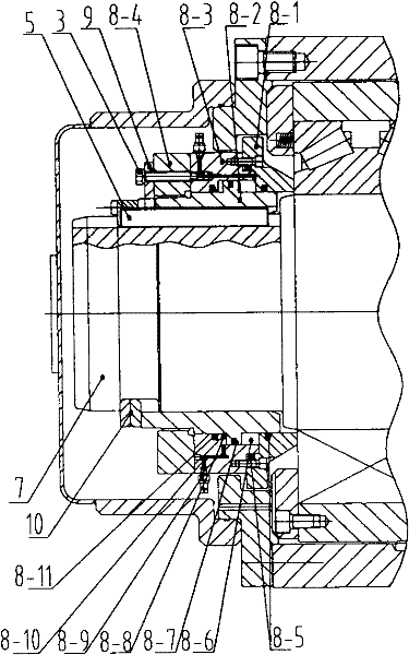
[0010] Such as figure 2 As shown, the oil film bearing hydraulic fast locking device of the present invention is composed of a short hydraulic cylinder, a locking plate 9, a square key 5, a snap ring assembly 10, a fastening bolt 3, etc., and the short hydraulic cylinder includes a cylinder Sleeve 8-1, piston 8-2, cylinder head 8-3, nut 8-4, cylinder liner seal 8-5, piston seal 8-7, cylinder head seal 8-11, quick change joint 8-9; The inner hole of the cylinder liner 8-1 is provided with a double-channel cylinder liner seal 8-5, the inner hole of the cylinder head 8-3 is provided with a single-channel cylinder head seal 8-11, and the oil hole 8-10 connecting the two oil chambers is arranged; the piston 8 -2 The inner hole is provided with a keyway; the cylinder liner 8-1, the piston 8-2, the cylinder head 8-3, the cylinder liner seal 8-5, the piston seal 8-7 and the cylinder head seal 8-11 are assembled together And form two oil chambers, that is, locking oil chamber 8-6, di...


PUM


Abstract

The invention relates to a hydraulic rapid locking device for an oil film bearing. The locking device comprises a short pattern hydraulic cylinder, a locking plate, a square key, a snap ring assembly etc., wherein the short pattern hydraulic cylinder comprises a cylinder sleeve, a piston, a cylinder cover, a nut, a sealing and a quick-change joint, etc. The locking device is characterized by changing a machinery locking into a hydraulic locking, wherein an original roller structure is maintained, and the machinery locking is changed into the hydraulic locking by utilizing present space; and a locking nut and a volution are omitted to change into a short pattern hydraulic cylinder structure. While loading and unloading of the oil film bearing, the quick-change joint on a hydraulic tool is connected to the short pattern hydraulic cylinder to start the hydraulic tool; pressure oil enters into a locking oil pocket or a dismounting oil pocket; and a locking pressure and a dismounting pressure are controlled quantificationally to complete bearing locking or dismounting. The locking device has effects of convenient loading and unloading, accurate quantification, rapidness and safety.

Description

technical field [0001] The invention relates to an oil film bearing, in particular to a hydraulic locking device for the oil film bearing. Background technique [0002] The locking device of the oil film bearing is to lock the bearing part of the oil film bearing on the roll to ensure the normal operation of the bearing assembly, and periodically disassemble the oil film bearing from the roll according to the requirements of grinding roll and maintenance. The locking device requires safe, convenient and fast operation during use. [0003] Such as figure 1 As shown, the existing locking device is a mechanical locking structure, which is mainly composed of a lock nut 1, a spiral ring 2, a fastening bolt 3, a locking plate 4, a square key 5, and a snap ring assembly 6. The lock nut 1 passes through The screw thread and the spiral ring 2 are assembled together, the square key 5 is installed in the keyway 7-1 of the roll 7 and embedded in the inner hole groove of the spiral rin...

Claims


Application Information

Patent Timeline
Patent Type & Authority Applications(China)
IPC IPC(8): F16C35/078
Inventor 王文波
Owner TAIYUAN HEAVY IND
Why Eureka
Try Eureka