Two-stage ejection refrigeration cycle system with economizer

A circulation system and economizer technology, which is applied in the field of refrigeration circulation system and two-stage injection refrigeration circulation system, can solve the problems of low ejector efficiency and achieve the effects of simple system structure, reduced throttling irreversible loss and improved performance

Active Publication Date: 2011-11-02
ZHEJIANG UNIV
View PDF6 Cites 11 Cited by
  • Summary
  • Abstract
  • Description
  • Claims
  • Application Information

AI Technical Summary

Problems solved by technology

[0005] The invention provides a two-stage injection refrigeration cycle system with an economizer, which uses the economizer and the first throttle valve to increase the cooling c

Method used


Image

  • Two-stage ejection refrigeration cycle system with economizer
  • Two-stage ejection refrigeration cycle system with economizer
  • Two-stage ejection refrigeration cycle system with economizer

Examples


Embodiment 1

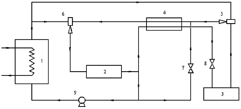
[0019] See figure 2 , figure 2 It is a schematic flowchart of an embodiment of the present invention. figure 2 The two-stage ejector refrigeration cycle system with economizer shown in includes generator 1, condenser 2, evaporator 3, economizer 4, first ejector 5, second ejector 6, first expansion valve 7, first Two expansion valve 8, solution pump 9. The first outlet of the generator 1 is divided into two paths. One refrigerant gas enters the first ejector 5 through the first inlet of the first ejector 5 as the working fluid, and the other refrigerant gas passes through the second ejector 6 as the working fluid. The first inlet enters the second ejector 6. The gas outlet of the second ejector 6 is connected to the inlet of the condenser 2, and the outlet of the condenser 2 is divided into three ways, the first way is connected with the first inlet of the economizer 4; the second way is connected with the inlet of the first expansion valve 7, After the outlet of the first e...

Embodiment 2

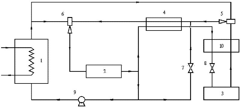
[0029] See image 3 , image 3 It is a schematic flow diagram of another embodiment of the present invention. image 3 The two-stage ejector refrigeration cycle system with economizer shown includes generator 1, condenser 2, evaporator 3, economizer 4, first ejector 5, second ejector 6, first expansion valve 7, second Expansion valve 8, solution pump 9, heat exchanger 10. The first outlet of the first generator 1 is divided into two paths. One refrigerant gas enters the first ejector 5 through the first inlet of the first ejector 5 as a working fluid, and the other refrigerant gas passes through the second ejector as a working fluid. The first inlet of 6 enters the second ejector 6. The gas outlet of the second ejector 6 is connected to the inlet of the condenser 2. The outlet of the condenser 2 is divided into three ways, the first way is connected with the first inlet of the economizer 4, and the second way is connected with the inlet of the first expansion valve 7. After...


PUM


Abstract

The invention discloses a two-stage ejection refrigeration cycle system with an economizer, and the system provided by the invention comprises the economizer and a first expansion valve, wherein the first outlet of a generator is divided into two paths; one path is connected with a first inlet of a first ejector; the other path is connected with a first inlet of the second ejector; the gas outlet of the second ejector is connected with a condenser; the outlet of the condenser is divided into three paths, wherein the first path is connected with a first inlet of the economizer, and the second path is connected with the inlet of the first expansion valve; after the outlet of the first expansion valve and the gas outlet of the first ejector are connected into one path, the outlet of the first expansion valve is connected with a second outlet of the economizer; the third path is connected with the inlet of the solution pump; the outlet of the solution pump is connected with the first inlet of the generator; the first outlet of the economizer is successively connected with the second expansion valve, the evaporator and a second inlet of the first ejector in series; and the second outlet of the economizer is connected with the second outlet of the second ejector. According to the two-stage ejection refrigeration cycle system, the economizer and the first throttle valve are utilized to achieve higher performance coefficients and refrigerating capacity.

Description

Technical field [0001] The invention belongs to the technical field of refrigeration and low temperature, and relates to a refrigeration cycle system, in particular to a two-stage injection refrigeration cycle system with an economizer. Background technique [0002] Energy is the basis for human survival and the most basic driving force for the development of the entire world. For example, fossil energy sources such as coal, oil, and natural gas provide sources of production materials and production power for industries such as steel, textiles, chemicals, and medical treatment. Energy is also the lifeline of the national economy and plays an important role in promoting the development of the country's industry. However, the world's energy supply is becoming increasingly tight, and energy issues have increasingly become the focus of national life and even the whole society. In the industrial production process, a large amount of waste heat is generated because its reusability is...

Claims


Application Information

Patent Timeline
IPC IPC(8): F25B41/06
Inventor 唐黎明李涛陈光明吴孔祥王征
Owner ZHEJIANG UNIV
Why Eureka
Try Eureka