High-resolution high-speed polarization difference imaging method

A polarization difference and high-resolution technology, applied in the optical field, can solve problems such as low system stability, reduced scanning rate and system resolution accuracy, and increased system error, so as to achieve good system stability, system error reduction, and resolution accuracy Improved effect

Inactive Publication Date: 2011-11-02
UNIV OF SHANGHAI FOR SCI & TECH
View PDF4 Cites 7 Cited by
  • Summary
  • Abstract
  • Description
  • Claims
  • Application Information

AI Technical Summary

Problems solved by technology

In prior art, see "K.A.Serrels, E.Ramsay, R.J.Warburton and D.T.Reid, Nanoscale optical microscopy in the vectorial focusing regime, nature photonics, vol.2, May2008, 311-314", in order to improve the resolution, in scanning In the long axis direction, a half-wave plate is mechanically inserted to change the polarization direction of the incident ray polarized light, but this will r

Method used


Image

  • High-resolution high-speed polarization difference imaging method
  • High-resolution high-speed polarization difference imaging method
  • High-resolution high-speed polarization difference imaging method

Examples


Embodiment Construction

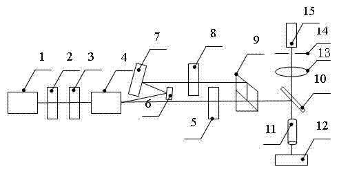
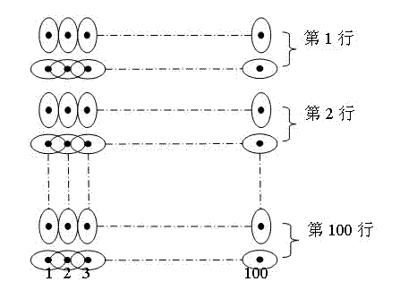
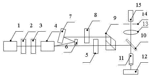
[0014] Usually, using polarization difference imaging, because the focusing produces an elliptical spot, according to the Rayleigh criterion, the system resolution in the direction of the short axis of the ellipse can only be increased. When the confocal microscope scans in the direction of the long axis, the scanning step needs to be longer, so that the system can The difference between two points is distinguished, so the system resolution is reduced instead, and the resolution of the entire system is determined by the size of the long axis. If a half-wave plate is mechanically inserted when scanning the long axis direction to change the polarization direction of the incident ray polarized light, although the system resolution in this direction can be improved, the scanning rate when the system changes the scanning direction will be reduced, and the Increase the system error, reduce the system resolution accuracy, and the stability is not high. The present invention utilizes ...


PUM


Abstract

The invention relates to a high-resolution high-speed polarization difference imaging method. In the method, linearly polarized light which can be controlled and of which the polarization directions are orthogonally changed at a high speed is generated by using characteristics of a high-speed time division deviated light path of an acousto-optic deflector and a characteristic that a lateral displacement polarization prism spectrometer integrates orthogonal line polarized light, system resolutions in the two directions are improved, and the high-speed polarization difference imaging method is formed. By the method, the defect that only the system resolution in one direction can be improved in the prior art is overcome; the scanning efficiency of a system is improved; system errors are reduced; resolving accuracy is improved; and the system has higher stability and high high-resolution imaging speed.

Description

technical field [0001] The invention relates to an optical technology, in particular to a high-resolution and high-speed polarization difference imaging method. Background technique [0002] Polarization difference imaging has important research significance in the field of optical microscopy imaging. For example, the confocal microscope system is a point-to-point imaging of the object-image conjugate. The focused laser beam scans the surface of the sample, while the photoelectric detection device receives the reflected light (or transmitted light) of the sample. The change of the sample structure makes the intensity of the reflected light (or transmitted light) Change, so that the output current of the photodetector changes, after signal processing, it is displayed on the computer screen synchronously. Since the irradiated linearly polarized light is focused by a lens with a high numerical aperture, an elliptical spot with a small area is produced, so there is no influence...

Claims


Application Information

Patent Timeline
IPC IPC(8): G01N21/17
Inventor 郭汉明田毅强黄猛翁晓羽姜曼蒋庭佳庄松林
Owner UNIV OF SHANGHAI FOR SCI & TECH
Why Eureka
Try Eureka