Online debugging method and debugging host

A technology for debugging a host and a debugging method, which is applied in the detection of faulty computer hardware and functional inspection, etc., can solve problems such as low debugging efficiency, and achieve the effects of improving debugging efficiency, slow response speed, and improving speed.

Inactive Publication Date: 2011-11-02
HISENSE HIVIEW TECH CO LTD
View PDF4 Cites 13 Cited by
  • Summary
  • Abstract
  • Description
  • Claims
  • Application Information

AI Technical Summary

Problems solved by technology

When EJTAG is used in conjunction with GDB, the EJTAG emulator is connected to the target machine and the host machine, and GDB is run on the host machine, all debugging work is done in the command line mode, so that the debugger has to manually Enter the corresponding debugging command, making the debugging efficiency low

Method used


Image

  • Online debugging method and debugging host
  • Online debugging method and debugging host
  • Online debugging method and debugging host

Examples


Embodiment 1

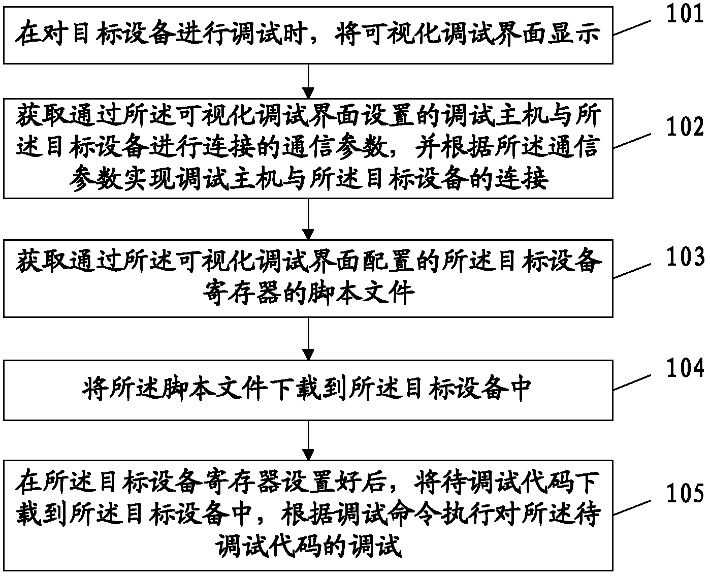
[0029] An embodiment of the present invention provides an online debugging method, such as figure 1 As shown, the method includes:

[0030] 101. When debugging the target device, display a visual debugging interface.

[0031] It should be noted that the embodiment of the present invention provides a visual debugging interface for users to debug operations, and users can use the visual debugging interface to set the communication parameters of the connection between the debugging host and the target device and the script file of the target device register. Wait. The representation form of the visualized operation interface is not limited in the embodiments of the present invention, and any visualized interface capable of man-machine interaction falls within the protection scope of the present invention.

[0032] 102. Acquire communication parameters for connecting the debugging host to the target device set through the visual debugging interface, and realize the connection be...

Embodiment 2

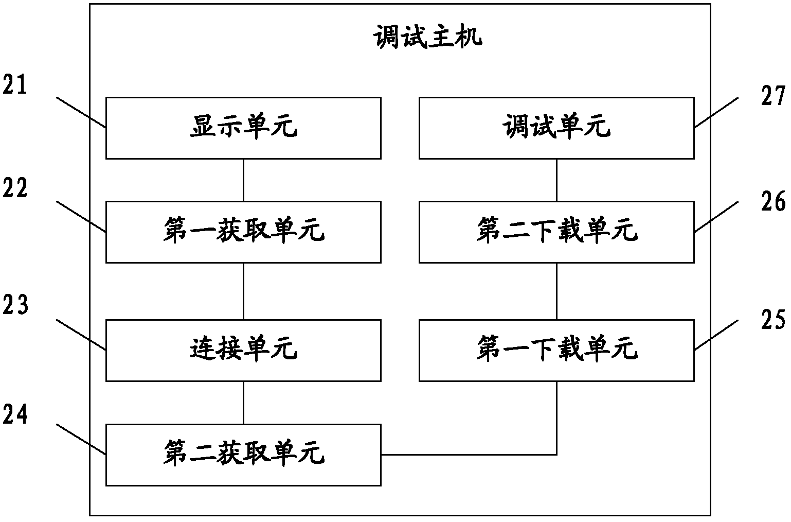
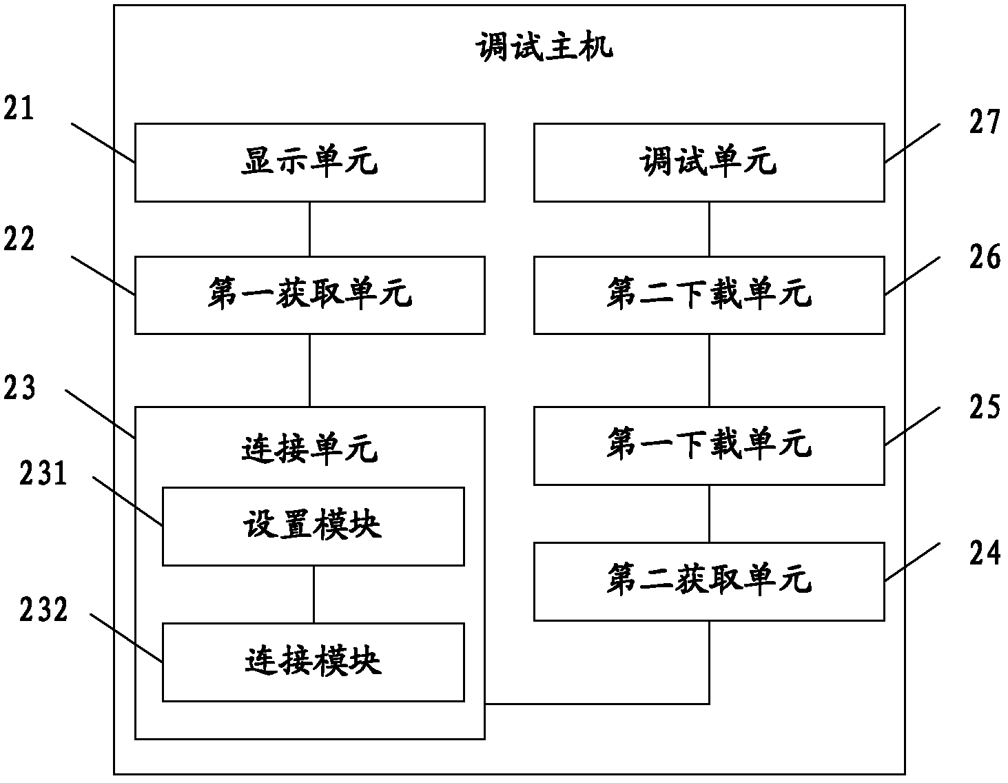
[0049] An embodiment of the present invention provides a debugging host, such as figure 2 As shown, the debugging host includes: a display unit 21 , a first acquiring unit 22 , a connecting unit 23 , a second acquiring unit 24 , a first downloading unit 25 , a second downloading unit 26 , and a debugging unit 27 .

[0050] The display unit 21 is configured to display a visual debugging interface when debugging the target device. Wherein, the representation form of the visual operation interface is not limited in the embodiment of the present invention, and any visual interface capable of man-machine interaction falls within the protection scope of the present invention.

[0051] The first obtaining unit 22 is configured to obtain communication parameters for connecting the debugging host and the target device set through the visual debugging interface. Wherein, the communication parameters include information such as an IP address of the target device, a communication type, ...


PUM


Abstract

The embodiment of the invention discloses an online debugging method and a debugging host and relates to the field of debugging of a processing chip. A visual debugging interface can be provided, the speed of inputting a debugging command is improved, the debugging response speed is low, and the debugging efficiency is improved. The method comprises the following steps of: displaying the visual debugging interface when target equipment is debugged; acquiring a communication parameter for connecting the debugging host with the target equipment, which is set through the visual debugging interface, and connecting the debugging host with the target equipment according to the communication parameter; acquiring a script file of a register of the target equipment, which is configured through the visual debugging interface; downloading the script file into the target equipment; and downloading a code to be debugged into the target equipment and executing debugging of the code to be debugged according to the debugging command after the register of the target equipment is set. The online debugging method is mainly used for the online debugging process based on a reduced instruction set computer (RISC) processor.

Description

technical field [0001] The invention relates to the field of processing chip debugging, in particular to an online debugging method and a debugging host. Background technique [0002] EJTAG (Enhanced Joint Test Action Group) is a specification based on the basic structure and function extension of the IEEE 1149.1 protocol. It is a hardware / software subsystem that implements a hardware-based Debug features to support on-chip debugging. The EJTAG interface uses the TAP (Test Access Port, Test Access Interface) access mode of JTAG (Joint Test Action Group, joint test behavior organization) to transfer test data into or out of the processor core. The functions that EJTAG can realize include: accessing processor registers, accessing system memory space, setting software / hardware breakpoints, single-step / multi-step execution, etc. The EJTAG debugging function module is composed of 4 parts: the component expansion inside the CPU core, the hardware breakpoint unit, the debugging c...

Claims


Application Information

Patent Timeline
Patent Type & Authority Applications(China)
IPC IPC(8): G06F11/26
Inventor 吴亚杰曾小光
Owner HISENSE HIVIEW TECH CO LTD
Why Eureka
Try Eureka