Power flow controller with failure current limiting function

A power flow controller, fault current limiting technology, applied in emergency protection circuit devices for limiting overcurrent/overvoltage, reactive power compensation, AC network to reduce harmonics/ripples, etc., can solve the problem of failure to achieve device protection , power grid failure, damage, etc.

Inactive Publication Date: 2013-11-06
INST OF ELECTRICAL ENG CHINESE ACAD OF SCI
View PDF7 Cites 0 Cited by
  • Summary
  • Abstract
  • Description
  • Claims
  • Application Information

AI Technical Summary

Problems solved by technology

Both types of power flow controllers can effectively control the flow of grid power, but they are powerless against grid faults, and short-circuit faults in the grid can even cause devastating damage to these devices themselves
image 3 The Chinese patent 200620069650.2 "unified power flow controller with short-circuit current limiting function" uses a variable impedance transformer with overcurrent magnetic circuit saturation characteristics to achieve fault current limiting, but this circuit cannot protect the device itself. may cause damage to the power electronic devices of the device itself

Method used


Image

  • Power flow controller with failure current limiting function
  • Power flow controller with failure current limiting function
  • Power flow controller with failure current limiting function

Examples


Embodiment Construction

[0015] The present invention will be further described below in conjunction with the accompanying drawings and specific embodiments.

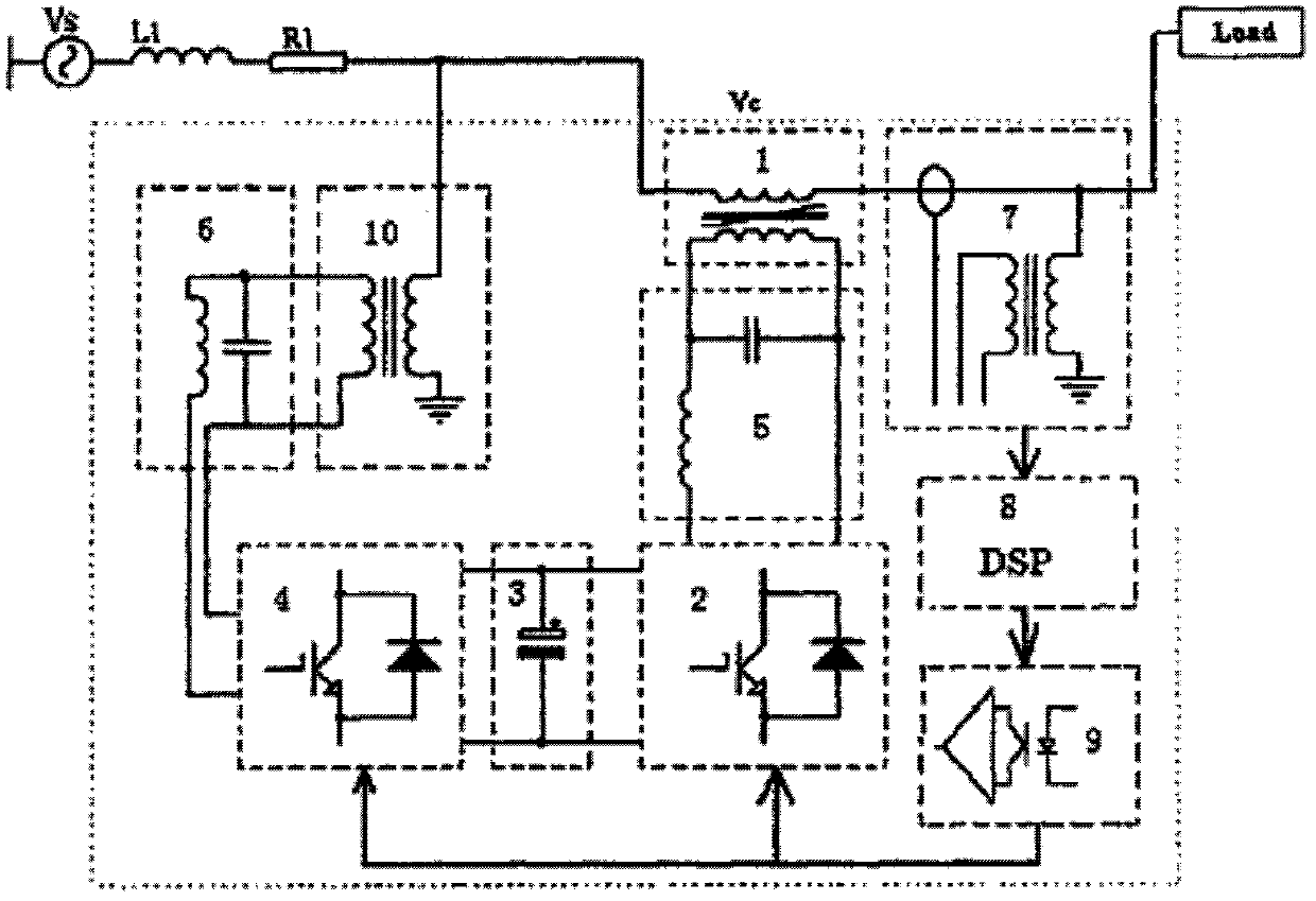
[0016] Figure 4 It is the topology structure of Embodiment 1 of the present invention. Such as Figure 4 As shown, the structure of Embodiment 1 of the present invention is as follows: the voltage source converter VSC and its three-phase filter circuit, the chopper and the three-phase step-down transformer Tr form a parallel power regulation system PCS; the voltage source converter VSC The three-phase AC voltage terminal is connected to the low-voltage side of the three-phase step-down transformer Tr through a filter circuit, and the high-voltage side of the three-phase step-down transformer Tr is connected to the first three-phase power supply Us; the DC voltage terminal of the voltage source converter VSC is connected to the DC After the capacitor C is connected in parallel with the DC voltage terminal of the chopper, the AC voltage termin...


PUM


Abstract

The invention discloses a power flow controller with a failure current limiting function. When a power grid does not fail, the power flow controller controls current on a current limiting inductor by a current transformer and regulates equivalent impedance flowing into the power grid, thereby controlling the transmission power of the power grid, and compensates the harmonic waves and reactive power of transmission current by the current transformer; and when the power grid fails, the current limiting inductor is directly connected in series to the power grid to function in failure current limiting, and simultaneously, the power flow controller also can control the current transformer to discharge the current limiting inductor and control the current of the current limiting inductor to better current limiting effects, and can perform steady current limiting by a current limiting bypass, with the current limiting inductor, of a protective circuit to better failure current limiting effects.

Description

technical field [0001] The invention relates to a power flow controller with fault current limiting function. Background technique [0002] Power flow control and fault current limiting are two core technical problems faced by the transmission network. At present, there are mainly two types of power flow controllers. One is to change the equivalent impedance of the line, such as figure 1 The U.S. Patent US00542495 "power flow control of transmission lines" shown in Fig. figure 2 Patent WO 9605642A1 "Universal fast power flow controller" is shown. These two types of power flow controllers can effectively control the flow of grid power, but they are powerless against grid faults, and short-circuit faults in the grid can even cause devastating damage to these devices themselves. image 3 The Chinese patent 200620069650.2 "unified power flow controller with short-circuit current limiting function" uses a variable impedance transformer with overcurrent magnetic circuit satura...

Claims


Application Information

Patent Timeline
Patent Type & Authority Patents(China)
IPC IPC(8): H02J3/01H02J3/18H02H9/02
CPCY02E40/30Y02E40/40
Inventor 郭文勇肖立业戴少涛张志丰
Owner INST OF ELECTRICAL ENG CHINESE ACAD OF SCI
Why Eureka
Try Eureka