Ultrawhite calendering glass kiln

A glass furnace and calendering technology, applied in glass furnace equipment, glass manufacturing equipment, manufacturing tools, etc., can solve problems such as changes, achieve the effects of improving stability, high production capacity, and avoiding lateral temperature differences

Inactive Publication Date: 2011-11-09
XINYI PHOTOVOLTAIC IND (ANHUI) HLDG CO LTD
View PDF9 Cites 36 Cited by
  • Summary
  • Abstract
  • Description
  • Claims
  • Application Information

AI Technical Summary

Problems solved by technology

Although this structure can use one glass melting furnace to drive multiple production lines to produce simultaneously and improve the melting capacity of the glass melting furnace, but due to the long distance from the melting furnace to the overflow port, the neck is located at the outlet end of the furnace. And it is a narrow and straight channel with a cross-sectional area much smaller than the furnace outlet. The glass melt flowing through it will cause a huge change in speed and flow due to the sudden narrowing of the channel area, and will produce a Eddy flow, because the glass liquid has a certain viscosity, which will lead to the change of the flow rate and temperature of the glass melt entering the branch channel, which will bring about the change of the flow rate and temperature of the glass liquid at the overflow port. At the same time, the melting furnace to the overflow port With a long distance, the molten glass has to travel long distances to reach the overflow port, which also leads to a lateral temperature difference at the overflow port. Due to the very high processing requirements for ultra-clear glass, this temperature difference will directly affect the glass liquid. Subsequent calendering processing and product quality

Method used


Image

  • Ultrawhite calendering glass kiln
  • Ultrawhite calendering glass kiln
  • Ultrawhite calendering glass kiln

Examples


Embodiment 1

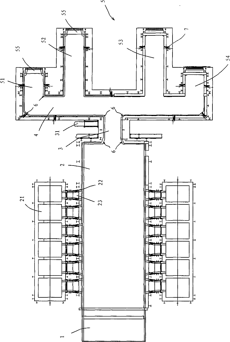
[0030] see figure 1 , the first embodiment of the present invention includes a melting furnace 2, a main flow channel 3, a cross flow channel 4 and four branch flow channels 51, 52, 53, 54 connected in sequence, that is, the molten glass enters the cross flow channel 4 through the main flow channel 3 and is then divided into four There are two branch flow channels, and the molten glass flows through two 90° corners during the flow process and then enters each branch flow channel. Of course, the direction of the branch channel 5 can be as follows figure 1 All shown are in the longitudinal direction, and the first and last branch flow channels can also be optionally extended in the horizontal direction, and overflow ports 55 are provided at the outlet ends of each branch flow channel 5 .

[0031] The main channel 3 in the first embodiment is a cylindrical, square or rectangular channel, and the main channel 3 or each branch channel 5 is provided with a transition surface 6 at a...

Embodiment 2

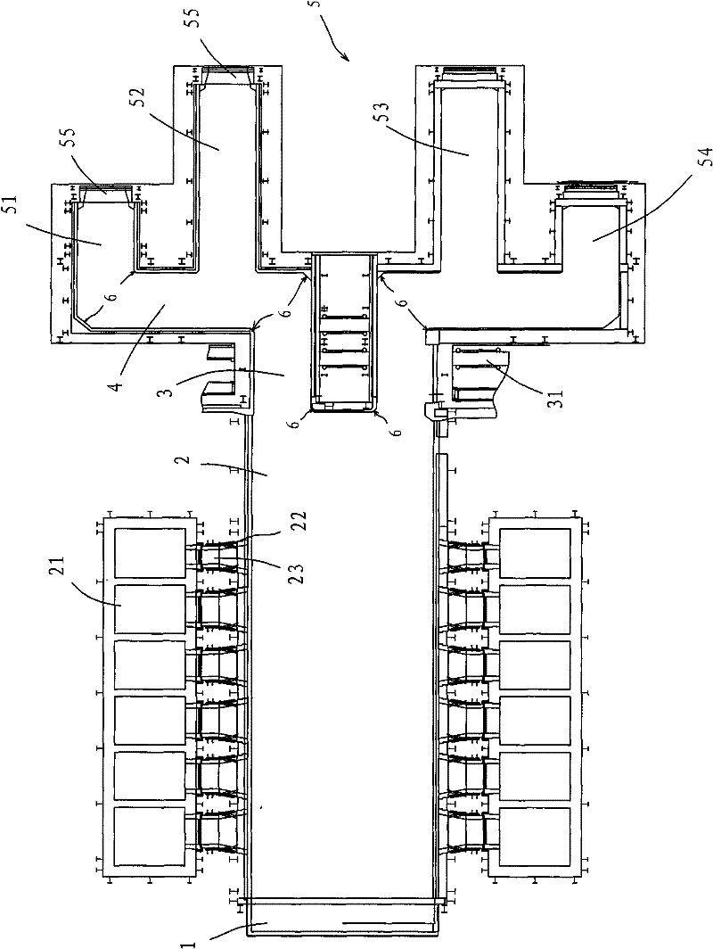
[0040] see figure 2 , the basic structure of the second embodiment is the same as that of the first embodiment, the difference is that the main flow channel 3 is divided into two channels (or more than two channels), which are symmetrically arranged at the outlet end of the melting furnace 1 and connected with the entrance of the cross flow channel 4 The ends are connected, and the cross flow channel 4 also adopts two separated flow channels. This is because, in the design of the ultra-clear glass production line, the flow path through which the molten glass flows should be as short as possible under the premise of meeting the calendering operation, that is to say, under the premise of meeting the various operations of the calender, the glass The stroke of the liquid to reach the forming position should be as short as possible. In the second embodiment, since the main channel 3 is divided into two channels, on the one hand, the intersection of the molten glass at the outlet ...

Embodiment 3

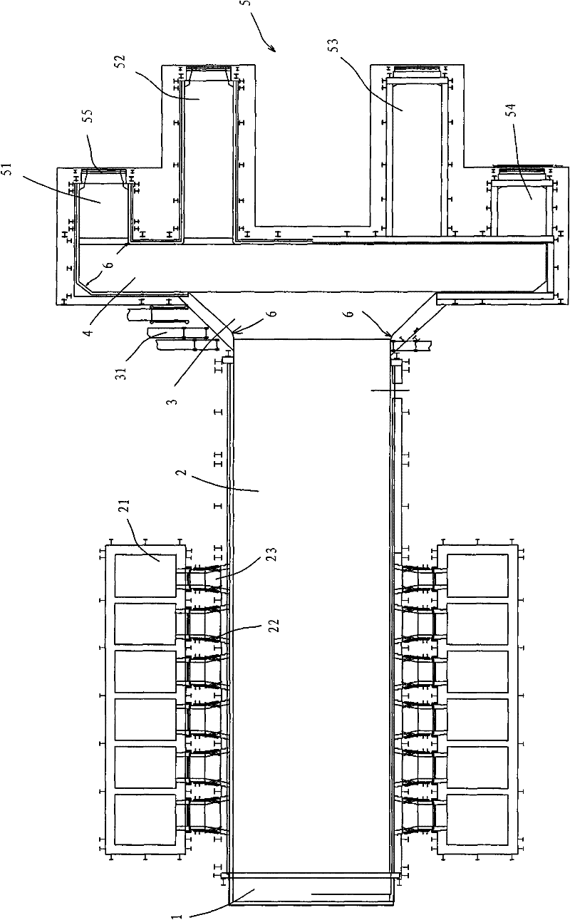
[0043] see Figure 3A-Figure 3C The basic structure of the second embodiment is also the same as that of the first embodiment, except that the main flow channel 3 is a reverse trumpet-shaped structure in which the cross-section of the outlet end of the melting furnace 2 is larger than that of the cross-flow channel 4 inlet end. In this way, the molten glass at the outlet end of the melting furnace 2 can have a gentle transition when flowing to the transverse channel 4, so as to avoid the huge change of the speed and flow rate of the molten glass due to the sudden narrowing of the channel area, so as to keep the molten glass flowing During the process, the temperature changes within a small range, so as to ensure that the temperature of the molten glass entering the subsequent calendering process is within the required range.

[0044] see Figure 3A , the cross-section of the main channel 3 inlet end of structure one of the present embodiment is equal to the cross-section of t...


PUM

PropertyMeasurementUnit
transmittivityaaaaaaaaaa

Abstract

The invention provides an ultrawhite calendering glass kiln. The kiln is characterized in that: the kiln comprises a melting furnace, a main channel, a lateral channel, and a plurality of branch channels, which are sequentially communicated; and the main channel is a cylinder channel which has a round/quadrate/rectangular/trumpet-like shape, and each corner of each channel is provided with a transition surface. According to the invention, passage sections of the main channel are improved, and simultaneously the corners of all channels are provided with the transition surfaces, so a function of one kiln corresponds to multiple lines is realized, rapid changes of the velocity and the flow of a glass melt caused by a sudden change of a channel area while the glass melt enters another channel when going through the main channel are retarded or reduced, and long-time eddy and scour of the glass melt on the corner can be avoided, thereby a lateral temperature difference generated in a process that the glass melt flows from the outlet of the melting furnace to overflow ports of the branch channels can be reduced or avoided, and the production quality and the quality stability are improved.

Description

technical field [0001] The invention relates to the technical field of ultra-clear rolled glass manufacturing, and more specifically relates to an ultra-clear rolled glass kiln. Background technique [0002] Ultra-clear rolled glass is a rolled glass with low iron content to achieve high transmittance. It is a high-quality, multi-functional new type of high-end glass with a light transmittance of over 91.5%. It is crystal clear, High-end and elegant features are mainly used in the interior and exterior decoration of high-end buildings, solar cell components, high-end gardening buildings, high-end glass furniture products and other industries. Ultra-clear rolled glass has all the processability of high-quality float glass at the same time, with superior physical, mechanical and optical properties, and can be processed in various deep processing like other high-quality float glass. The unparalleled superior quality and product performance make ultra-clear glass have broad app...

Claims


Application Information

Patent Timeline
Patent Type & Authority Applications(China)
IPC IPC(8): C03B5/00
Inventor 董清世黄华义辛崇飞刘笑荣徐小明
Owner XINYI PHOTOVOLTAIC IND (ANHUI) HLDG CO LTD
Why Eureka
Try Eureka