Hydraulic energy-saving multi-well pumping unit

A pumping unit and hydraulic technology, applied in wellbore/well components, production fluid, earthwork drilling and production, etc., can solve the problems of huge equipment, increased cost, heavy weight, etc.

Inactive Publication Date: 2011-11-09
陈万仁
View PDF8 Cites 8 Cited by
  • Summary
  • Abstract
  • Description
  • Claims
  • Application Information

AI Technical Summary

Problems solved by technology

[0002] The traditional pumping unit has the advantages of simple structure, strong and durable. However, the traditional pumping unit is a purely mechanical movement, which needs to be self-balanced. The balance depends on the heavy mechanical balance. , high energy consumption, and can only complete its working cycle according to certain parameters (such as stroke, stroke times, etc.) that are not easy to change during operation
It is difficult to achieve reasonable coordination between surface equipment and downhole equipment
In order to reduce energy consumption, the patent application No. ZL200920032400.5 discloses an intelligent energy-saving hydraulic internal balance pumping unit

Method used


Image

  • Hydraulic energy-saving multi-well pumping unit
  • Hydraulic energy-saving multi-well pumping unit
  • Hydraulic energy-saving multi-well pumping unit

Examples


Embodiment 1

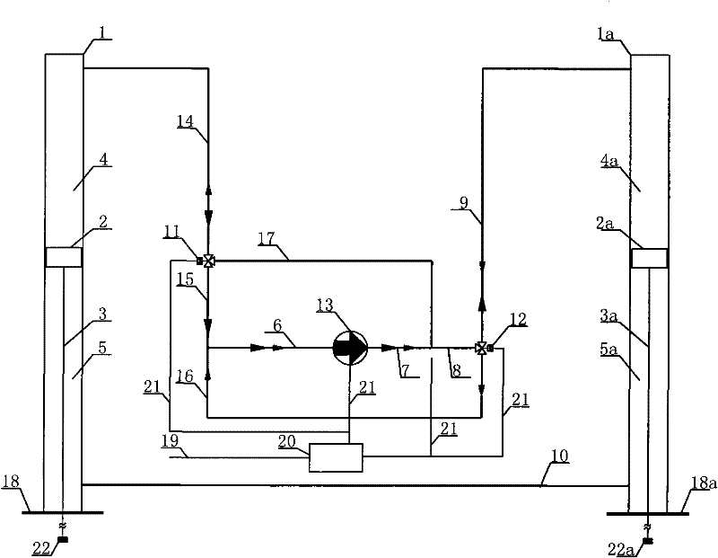
[0017] Embodiment 1: The hydraulic energy-saving multi-well pumping unit in this embodiment includes a hydraulic system, an automatic reversing valve, an oil well sucker rod connector, a control cabinet, and connecting pipelines. There are two corresponding single pumping units in the hydraulic system. Piston rod double-acting hydraulic cylinders 1 and 1a are equipped with piston 2 and piston 2a respectively in hydraulic cylinders 1 and 1a, and the lower parts of piston 2 and piston 2a are respectively fixed with lower piston rod 3 and lower piston rod 3a; In cylinder 1, the part of the hydraulic cylinder above the piston 2 is called the upper push cylinder 4, and the part of the hydraulic cylinder below the piston 2 is called the lower push cylinder 5; in the other hydraulic cylinder 1a, the part of the hydraulic cylinder above the piston 2a is called the upper push cylinder. The hydraulic cylinder 4a below the piston 2a is called the lower hydraulic cylinder 5a; the base 18 i...

Embodiment 2

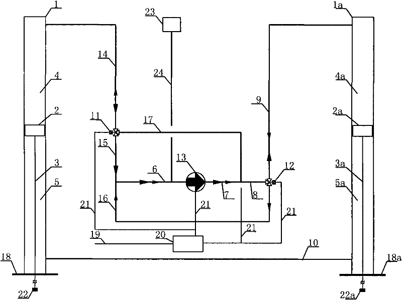
[0019] Embodiment 2: The structure of this embodiment is that a liquid replenishment pipe 24 and a liquid replenishment tank 23 are installed on the pipeline 6 connected to the inlet end of the hydraulic pump 13 . Other structures are the same as in Embodiment 1.

Embodiment 3

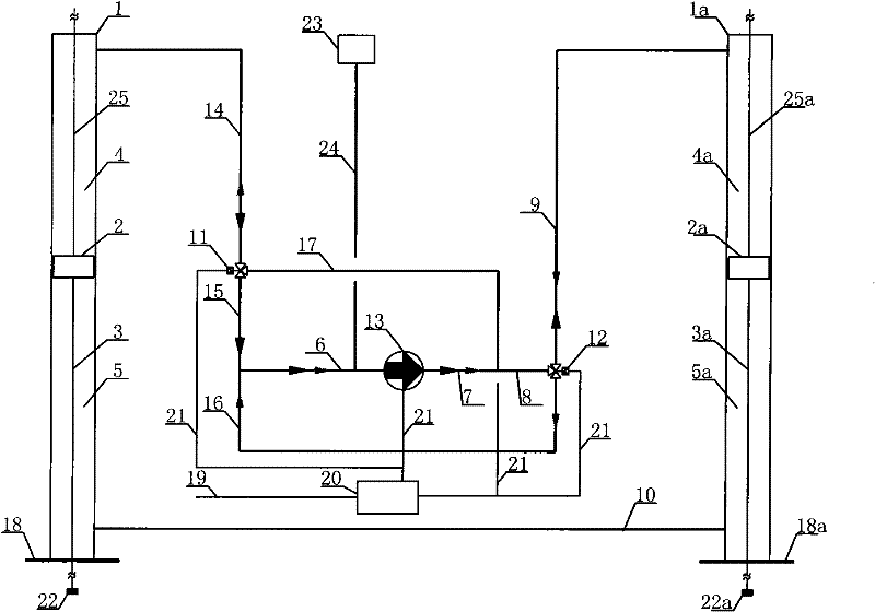
[0020] Embodiment 3: The hydraulic cylinder in this embodiment is a double-piston-rod double-acting hydraulic cylinder. The upper part of the piston 2 in the hydraulic cylinder 1 in this embodiment is fixed with a piston rod 25; the piston 2a in the hydraulic cylinder 1a The top is fixed with a piston rod 25a. Other structures are the same as in Embodiment 2.


PUM


Abstract

The invention discloses a hydraulic energy-saving multi-well pumping unit which comprises a hydraulic system, automatic reversing valves, an oil well sucker rod connector, a control cabinet and connecting pipelines, wherein at least two hydraulic cylinders are connected with a hydraulic pump through the connecting pipeline; each hydraulic cylinder is a double-acting hydraulic cylinder; the automatic reversing valves are respectively arranged on an inlet pipeline and an outlet pipeline of the hydraulic pump; lower push-in cylinders of all the double-acting hydraulic cylinders are communicated with one another; upper push-in cylinders of the hydraulic cylinders are divided into two relatively-balanced parts; each part is connected with the automatic reversing valve through the pipeline and is communicated with the inlet pipeline and the outlet pipeline at two ends of the hydraulic pump through the pipelines; and a connector connected with an oil well sucker rod is arranged at the lower end of a lower piston rod at the lower part of a hydraulic cylinder piston. The hydraulic energy-saving multi-well pumping unit has the advantage of low manufacturing cost and provides a powerful support for the popularization of an exploiting and energy-saving technology of an oil field; and compared with the traditional beam-pumping unit, the hydraulic energy-saving multi-well pumping unit is adopted to save steel by 40-90 percent, save energy by 30-70 percent and ensure that the stroke is 0-8 meters and the stroke frequency is 1-20 times.

Description

technical field [0001] The invention belongs to an oil pumping unit of oil exploitation equipment. In particular, it relates to a hydraulic energy storage pumping unit. Background technique [0002] The traditional pumping unit has the advantages of simple structure, strong and durable. However, the traditional pumping unit is a purely mechanical movement, which needs to be self-balanced. The balance depends on the heavy mechanical balance. , high energy consumption, and can only complete its working cycle according to certain parameters (such as stroke, stroke times, etc.) that are not easy to change during operation. It is difficult to achieve reasonable coordination between surface equipment and downhole equipment. In order to reduce energy consumption, the patent application No. ZL200920032400.5 discloses an intelligent energy-saving hydraulic internal balance pumping unit for sister wells. The effect of reducing energy consumption; but this equipment can only be used...

Claims


Application Information

Patent Timeline
IPC IPC(8): E21B43/00
Inventor 陈万仁
Owner 陈万仁
Why Eureka
Try Eureka