Fuel nozzle

A technology of fuel nozzles and injection holes, which is applied in the direction of fuel injection devices, charging systems, engine components, etc., to achieve the effects of improving flow coefficient, uniform mixture, and large diffusion range

Inactive Publication Date: 2011-11-09
DALIAN UNIV OF TECH
View PDF0 Cites 5 Cited by
  • Summary
  • Abstract
  • Description
  • Claims
  • Application Information

AI Technical Summary

Problems solved by technology

Increasing the injection pressure is an important method to increase the turbulence intensity at the outlet of the nozzle hole to improve the atomization quality, especially some diesel engines have used an injection pressure above 200MPa, but further increasing the injection pressure is limited by factors such as material strength and power consumption

Method used


Image

  • Fuel nozzle
  • Fuel nozzle
  • Fuel nozzle

Examples


Embodiment Construction

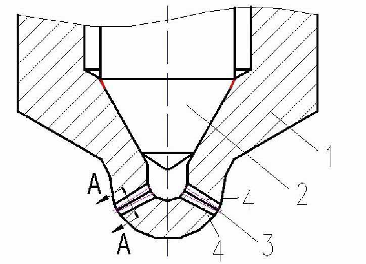
[0014] figure 1 A structure of a fuel nozzle is shown. This kind of fuel nozzle is composed of a needle valve body 1 and a needle valve 2, and a combination injection hole 3 is arranged on the head of the needle valve body 1, and each combination injection hole 3 is composed of at least two sub injection holes 4 gathered together. According to the matching requirements of combustion, there may be 1 to 16 combined injection holes 3 and 2 to 8 sub-injection holes 4 . The sub-spray hole 4 adopts a cylindrical small hole or a conical small hole. The combined nozzle hole 3 can have many different structural forms: the shape factor of the nozzle hole outlet is combined in different ways with the nozzle hole 4, and may have many different shapes.

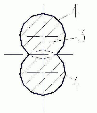
[0015] figure 2 It is shown that the combined nozzle hole 3 is formed by the intersection of two sub-nozzle holes 4, and the area shown by the section line in the figure is the flow area of ​​the combined nozzle hole 3 on the A-A secti...


PUM


Abstract

The invention discloses a fuel nozzle, belonging to a fuel spraying device of an internal-combustion engine fuel system. The fuel nozzle is composed of a needle valve body and a needle valve, wherein the head of the needle valve body is provided with at least one combined spray orifice; each combined spray orifice is composed of at least two sub spray orifices; the cross sections of the sub spray orifices are tangent; and the central lines of the sub spray orifices can be parallel or can be in different planes. Because fuel in the combined orifices can have intense disturbance, turbulence kinetic energy is increased so as to improve atomization; and atomization throughout distance is regulated by changing the injection direction of each sub spray orifice so as to improve flow coefficient. By the arrangement of the spray orifices, internal turbulence intensity is improved, atomization is improved, the throughout distance can be regulated, the spatial distribution range of sprayed mist is expanded, the quality of mixed gas is improved, and the effect of quick, sufficient and complete combustion can be achieved, therefore the economic performance, the emission performance and the power performance of the engine can be further improved.

Description

technical field [0001] The invention relates to a fuel nozzle, which belongs to the fuel injection device of the internal combustion engine fuel system. Background technique [0002] It is well known that the performance of the fuel injection system of an internal combustion engine is the most critical factor affecting the quality of mixture formation, and thus also the dominant factor affecting the economy and emission of the internal combustion engine. Existing studies have shown that the fuel spray characteristics of internal combustion engines are affected by the cavitation and turbulence in the nozzle hole, and the greater the turbulence intensity near the outlet inside the nozzle hole, the better the spray atomization effect. Increasing the injection pressure is an important method to increase the turbulence intensity at the outlet of the nozzle hole to improve the atomization quality, especially some diesel engines have used an injection pressure above 200MPa, but fur...

Claims


Application Information

Patent Timeline
Patent Type & Authority Applications(China)
IPC IPC(8): F02M61/18
Inventor 隆武强冷先银董全
Owner DALIAN UNIV OF TECH
Why Eureka
Try Eureka