Buffer relief valve for hydraulic motor

A technology of hydraulic motor and relief valve, used in servo motor components, fluid pressure actuation devices, mechanical equipment, etc., can solve the vibration and noise of hydraulic system and components, damage, can not better protect the service life of hydraulic components, etc. problems, to achieve the effect of smooth startup, protection of system safety, and improvement of operating performance

Inactive Publication Date: 2011-11-09
SAIKESI HYDRAULIC TECH CO LTD
View PDF5 Cites 23 Cited by
  • Summary
  • Abstract
  • Description
  • Claims
  • Application Information

AI Technical Summary

Problems solved by technology

Hydraulic shock will cause vibration and noise to the entire hydraulic system and components, and even damage
In the prior art, people generally use the swing motor relief valve to limit the maximum working pressure of the swing system, but it is difficult for

Method used


Image

  • Buffer relief valve for hydraulic motor
  • Buffer relief valve for hydraulic motor
  • Buffer relief valve for hydraulic motor

Examples


Embodiment Construction

[0018] Embodiments of the present invention will be described in further detail below in conjunction with the accompanying drawings.

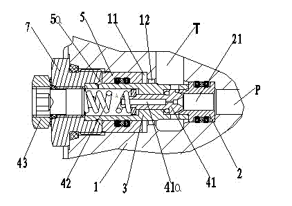
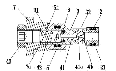
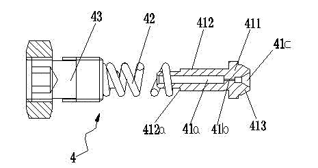
[0019] Figure 1 to Figure 4 Shown is the structural representation of the present invention.

[0020] The reference signs are: oil inlet P, oil return port T, valve body 1, slide chamber 11, oil passage 12, valve seat 2, connection hole 21, valve sleeve 3, fluid chamber 3a, slide rod guide hole 3b , compression chamber 3c, radial damping hole 31, oil outlet hole 32, spool assembly 4, spool 41, axial through hole 41a, first damping hole 41b, tapered hole 41c, valve head 411, valve stem 412, convex Table top 412a, sealing ball head 413, compression spring 42, adjustment bolt 43, buffer piston 5, buffer cavity 5a, pressure pad 6, screw plug 7, reaming table top 7a.

[0021] Such as Figure 1 to Figure 4 As shown, a buffer relief valve for a hydraulic motor of the present invention includes a matched valve body 1, a valve seat 2, a valve sleeve...


PUM


Abstract

The invention discloses a buffer relief valve for a hydraulic motor, which comprises a valve body, a valve seat, a valve sleeve and a screw plug which are matched mutually, wherein the valve sleeve is provided with a valve plug assembly; a buffer piston is sleeved in a sliding cavity position on the valve body on the outer peripheral surface of the valve sleeve in a sliding manner and is provided with a buffer cavity with the screw plug formed at the left end opening of the valve body; the buffer cavity is communicated with an oil inlet of the valve body by a radial damping hole formed by the valve sleeve and an axial hole of the valve plug assembly; and the buffer piston realizes the buffer function of the relief valve by differential pressure delay caused by right shift. The relief valve is compact in a structure and easy to manufacture, and can improve the hydraulic impact of the hydraulic rotation motor during starting and braking and the operability of the hydraulic rotation motor obviously so as to improve prolong the service life of system hydraulic elements.

Description

technical field [0001] The invention relates to the technical field of mechanical and hydraulic control, in particular to an overflow valve, in particular to a buffer overflow valve for a hydraulic motor. Background technique [0002] In the construction machinery system, when there are many slewing mechanisms in motion, due to the large moment of inertia of the upper vehicle, it will cause a large hydraulic shock when starting, braking or suddenly changing direction. Especially when encountering an obstacle and suddenly stopping during the turning process, the hydraulic shock is more obvious. Hydraulic shock can cause vibration and noise to the entire hydraulic system and components, and even damage. In the prior art, people generally use the swing motor relief valve to limit the maximum working pressure of the swing system, but it is difficult for ordinary relief valves to completely eliminate or absorb the hydraulic shock when the system starts or brakes, so it cannot fu...

Claims


Application Information

Patent Timeline
IPC IPC(8): F15B13/02
Inventor 高志明吴赛珍
Owner SAIKESI HYDRAULIC TECH CO LTD
Why Eureka
Try Eureka