Hydraulic pressure control apparatus for vehicle with automatic transmission

一种自动变速器、油压控制的技术,应用在传动装置、流体传动装置、传动装置控制等方向,能够解决不能管理蓄压状态、难以得到响应性等问题,达到高响应性的效果

Inactive Publication Date: 2011-11-09
JATCO LTD +1
View PDF5 Cites 24 Cited by
  • Summary
  • Abstract
  • Description
  • Claims
  • Application Information

AI Technical Summary

Problems solved by technology

Therefore, there is a problem that it is difficult to obtain a smooth start characteristic with high responsiveness.
[0011] This can be said to be the following reason. The accumulator is in the pressure storage state only by a predetermined amount of elastic deformation of the elastic body that urges the piston, and the pressure storage state that changes every moment cannot be managed.

Method used


Image

  • Hydraulic pressure control apparatus for vehicle with automatic transmission
  • Hydraulic pressure control apparatus for vehicle with automatic transmission
  • Hydraulic pressure control apparatus for vehicle with automatic transmission

Examples


Embodiment Construction

[0080]Next, embodiments of the present invention will be described.

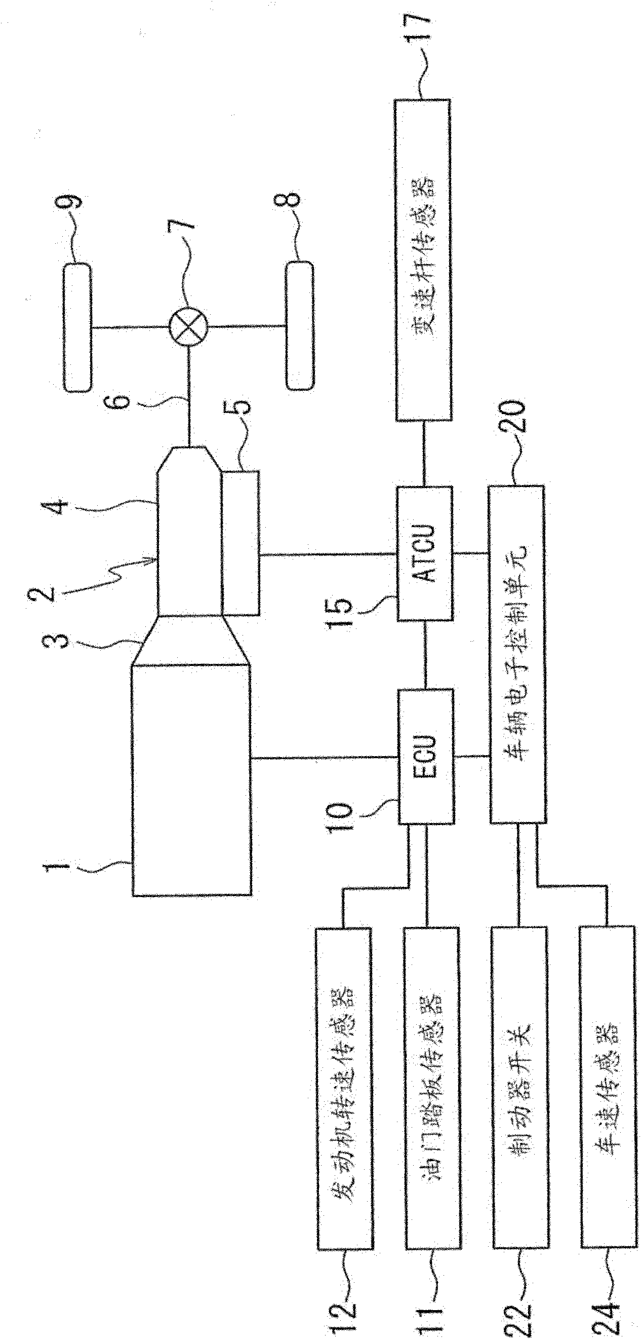
[0081] figure 1 It is a figure which shows the drive system of the vehicle of embodiment.

[0082] An automatic transmission 2 is connected to an output shaft of the engine 1 , and the automatic transmission 2 is composed of a torque converter 3 , a transmission mechanism unit 4 , and a hydraulic control valve unit 5 . The output of automatic transmission 2 is transmitted from drive shaft 6 to drive wheels 8 , 9 via differential gear 7 .

[0083] An engine control unit (ECU) 10 for controlling the ignition timing and the like is connected to the engine 1, and is connected to the automatic transmission 2 to control the clutch for realizing the target shift position. Automatic transmission control unit (ATCU) 15 for oil pressure, etc.

[0084] A vehicle electronic control unit 20 is connected to the engine control unit 10 and the automatic transmission control unit 15 .

[0085] An accelerator opening degr...


PUM


Abstract

The invention relates to a hydraulic pressure control apparatus for a vehicle with an automatic transmission, so as to improve the restarting response of the vehicle with the automatic transmission which effectively makes use of the idling stop of an accumulator. A hydraulic pressure loop of the automatic transmission is connected with the accumulator via an electromagnetic cut valve. At the time (t1) when an engine is restarted from the idling stop, the electromagnetic cut valve is switched to the ON position, and hydraulic pressure is discharged from the accumulator to a main pressure hydraulic way, so as to compensate the hydraulic pressure of an oil pump. A stroke sensor for detection of the stroke amount of a piston of the accumulator is attached in the accumulator. When a change in the amount of the stroke is reversed from such a direction as to discharge the hydraulic pressure to such a direction as to supply the hydraulic pressure, the electromagnetic cut valve is switched to the OFF position at the time (t3). In this way, during the time period in which the hydraulic pressure from the oil pump is increased, the hydraulic pressure is not supplied to accumulator, so that the hydraulic pressure from the oil pump can be supplied to hydraulic pressure loop exclusively so as to increase the hydraulic pressure. As a result, a stroke reducing process in a clutch can be allowed to quickly proceed to thereby obtain a high response ability.

Description

technical field [0001] The present invention relates to a hydraulic control device for a vehicle equipped with an automatic transmission that performs an idling stop. Background technique [0002] An automatic transmission includes clutches and brakes (hereinafter only represented by clutches) as a plurality of engagement devices that operate by pressing friction plates with hydraulic pressure in its gear train, and realizes a plurality of shift speeds through the combination of engagement and release of the engagement devices. For example, a low clutch (LOW / C) and a high clutch (HIGH / C) are provided, and the low clutch is engaged in the first forward speed, and the low clutch is released and the high clutch is engaged in the high third speed. [0003] The clutch has an oil pressure chamber and a piston stroked by the oil pressure supplied to the oil pressure chamber. During its operation, there are the following stages: a filling stroke up to the idling interval where the p...

Claims


Application Information

Patent Timeline
Patent Type & Authority Applications(China)
IPC IPC(8): F16H61/00F16H61/38F15B1/02F16H59/26F16H61/02
CPCF16H2061/0034F16H2312/14F16H61/0021F16H61/4096
Inventor 加藤芳章
Owner JATCO LTD
Why Eureka
Try Eureka