Air-cooled liquid-cooled combined radiating device

A heat dissipation device and combined technology, which is applied to cooling/heating devices of lighting devices, lighting devices, lighting and heating equipment, etc., can solve problems such as short lifespan, large size, and high quality, so as to reduce the bearing strength and ensure Cooling effect, easy installation effect

Active Publication Date: 2014-06-18
ZHANGPU BISU LIGHTING TECH
View PDF4 Cites 3 Cited by
  • Summary
  • Abstract
  • Description
  • Claims
  • Application Information

AI Technical Summary

Problems solved by technology

[0002] The current heat dissipation device mainly relies on two ways to achieve the purpose of heat dissipation: one is air cooling, which installs a larger power fan on the radiator, uses forced air cooling to improve the effect of heat dissipation and effectively reduces the size of the radiator, but this item The problem that the technology will encounter in practical application is that the fan itself is a component with a short lifespan, so the reliability of the entire system will be greatly reduced due to the failure of the fan; The number and volume of the slices will increase the cost
The other is liquid cooling, which is usually connected to a heating element required for heat dissipation on one surface, and its shell is in a cup-shaped structure. In order to ensure the heat dissipation effect, the shell is generally larger in size, and the cooling liquid is filled in the shell. In the cup-shaped cavity, the mass is relatively large, and there are many limitations in transportation and installation. In addition, the radiator generally needs to be installed on the bracket to obtain corresponding support, so that the bracket needs to have a large load-bearing capacity.

Method used


Image

  • Air-cooled liquid-cooled combined radiating device
  • Air-cooled liquid-cooled combined radiating device
  • Air-cooled liquid-cooled combined radiating device

Examples


Embodiment 1

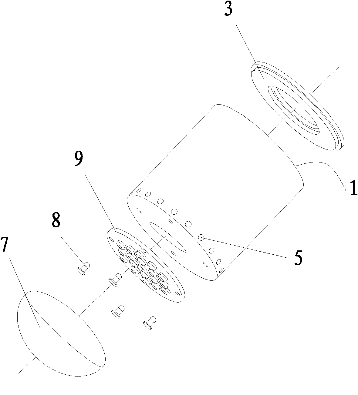
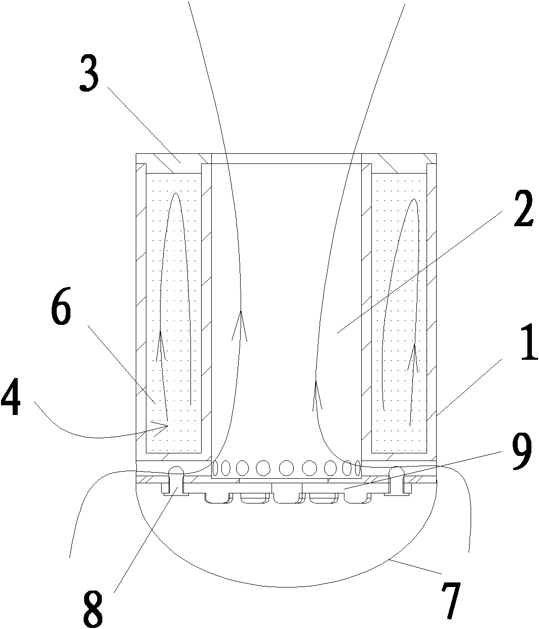
[0020] Such as figure 1 , figure 2 As shown, an air-cooled and liquid-cooled combined heat dissipation device described in this embodiment includes a housing 1 with a connecting surface of a heating element, and the housing 1 is a sandwich structure with an inner and an outer heat dissipation chamber with one end open. , the outer heat dissipation chamber 4 contains heat dissipation liquid 6, the inner heat dissipation chamber 2 is provided with an open air flow channel communicating with the outside world, and a sealing cover 3 covers the outer heat dissipation chamber 4. The housing 1 is a hollow cylinder, and the hollow part is the inner heat dissipation cavity 2 . A plurality of air guide holes 5 are opened below the side wall of the housing 1 to form the inlets of the air flow passages and the air guide holes 5 are evenly distributed in the circumferential direction, and the outlets of the air flow passages are arranged on the upper surface of the housing 1 . The seali...

Embodiment 2

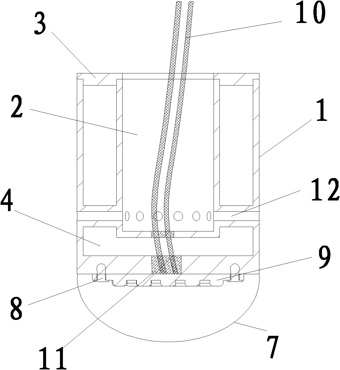
[0024] Such as Figure 4 , Figure 5 As shown, in the air-cooled and liquid-cooled combined heat dissipation device described in this embodiment, the outer heat dissipation cavity 4 is a hollow rectangular cavity, and the sealing cover 3 has a hole in the middle and is stepped. The surface is fastened to the open end of the outer heat dissipation chamber 4. The entrance of the inner heat dissipation cavity 2 is formed by an air guiding groove, which is arranged on the connecting surface of the heating body of the housing 1 . This structure is suitable for heat sinks that do not prevent gas from flowing through the bottom of the housing 1 . As shown in the figure, the present invention can connect the LED substrate 9 with the rivet 8 on the lower surface of the casing 1, and then put the lampshade 7 on it. Both the LED substrate 9 and the lampshade 7 are provided with air-conducting through holes.


PUM


Abstract

The invention discloses an air-cooled liquid-cooled combined radiating device, relates to a radiator and solves the technical problem that the conventional radiator has larger dimension and heavier weight in order to achieve a better radiating effect. The device comprises a shell connected with a heating body, and is characterized in that: the shell has an interlayer structure of inner and outer radiating cavities; one end of each radiating cavity is open; radiating liquid is accommodated in one of the inner and outer radiating cavities and an airflow channel is formed in the other of the inner and outer radiating cavities; and a sealing cover covers an accommodating cavity of the radiating liquid. By the air-cooled liquid-cooled combined radiating device, due to the interlayer structure, an airflow radiating channel is formed in one radiating cavity, a liquid radiating cavity is formed in the other radiating cavity, gas heat dissipation and liquid heat dissipation are better combined together, a radiating effect is guaranteed, the radiator is light in self weight and convenient to install and transport, and the bearing strength of a bracket for bearing the radiator can be reduced.

Description

technical field [0001] The invention relates to a radiator, in particular to an air-cooled and liquid-cooled combined radiator. Background technique [0002] The current heat dissipation device mainly relies on two ways to achieve the purpose of heat dissipation: one is air cooling, which installs a larger power fan on the radiator, uses forced air cooling to improve the effect of heat dissipation and effectively reduces the size of the radiator, but this item The problem that the technology will encounter in practical application is that the fan itself is a component with a short lifespan, so the reliability of the entire system will be greatly reduced due to the failure of the fan; The number and volume of the slices increase the cost. The other is liquid cooling, which is usually connected to one surface of the heating element required for heat dissipation, and its shell has a cup-shaped structure. In order to ensure the heat dissipation effect, the shell is generally la...

Claims


Application Information

Patent Timeline
Patent Type & Authority Patents(China)
IPC IPC(8): F21V29/00F21V29/56F21V29/83
Inventor 华桂潮姜熠
Owner ZHANGPU BISU LIGHTING TECH
Why Eureka
Try Eureka