
Aspheric surface measuring apparatus

A measuring device and aspheric technology, which are applied to measuring devices, optical devices, geometric characteristics/aberration measurement, etc., can solve the problems of inconvenient measurement of aspheric surfaces, difficulty in ensuring micro-motion accuracy, and inability to obtain motion accuracy. , to achieve the effect of improving measurement accuracy, preventing sudden changes in temperature and humidity, and high motion accuracy

Inactive Publication Date: 2011-11-09
FUJIFILM CORP
View PDF1 Cites 6 Cited by
  • Summary
  • Abstract
  • Description
  • Claims
  • Application Information

AI Technical Summary

Problems solved by technology

However, the problem with this method is that it is difficult to perform optical interferometry with high accuracy in a short period of time without restrictions on the measurement conditions
[0009] More specifically, when the mechanism for rotating the sample around the central axis of the aspheric shape and the mechanism for changing the angle between the central axis of the sample and the measurement optical axis of the interference optical system are combined for relatively moving the sample in three-dimensional directions And when interfering with the mechanism of the optical system, since the inertial force increases with the weight of the moving part, it becomes difficult to ensure the accuracy of micro-movement
As a result, the motion precision required for shape measurement with high precision cannot be obtained
In addition, the above-mentioned aspheric surface measurement is inconvenient due to restrictions on measurement conditions, long measurement time, and the like

Method used


Image

  • Aspheric surface measuring apparatus
  • Aspheric surface measuring apparatus
  • Aspheric surface measuring apparatus

Examples


Embodiment Construction

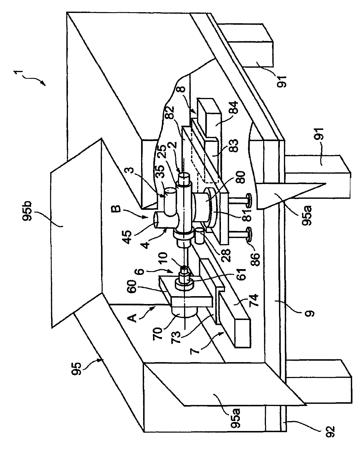
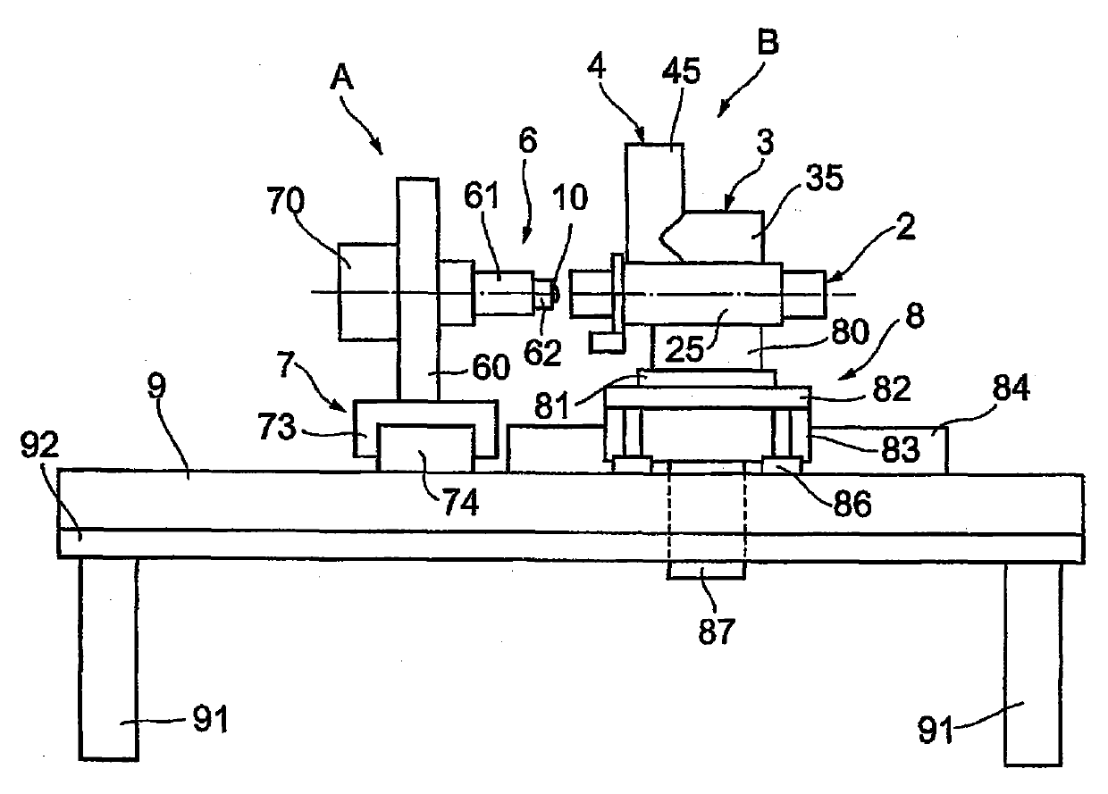
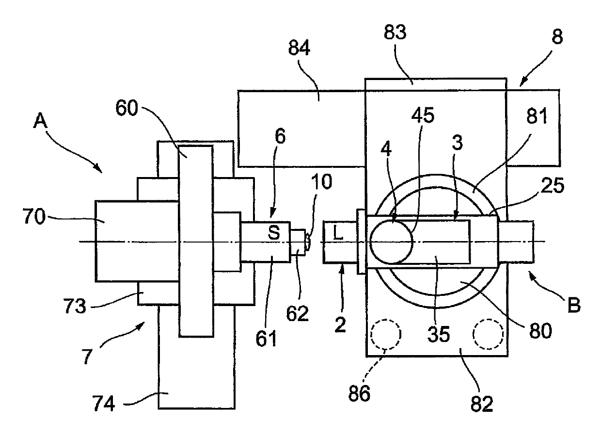
[0038] Hereinafter, embodiments of the present invention will be described in detail with reference to the drawings. noticed Figure 5 The schematic diagram of the structure is to show the precise shape and structure; when appropriate, according to Figure 1-4 Make changes to the dimensions of the components and the distances between the components as illustrated in .

[0039] Should Figure 1-5 The aspheric surface measuring device 1 of this embodiment shown in , measures and analyzes a rotationally symmetric aspheric surface 10a of a sample (aspheric lens) 10 (see Figure 5 )shape. The aspheric measuring device 1 comprises an interference optical system 2, a first imaging system 3, a second imaging system 4, a measurement analysis system 5 (see Figure 5 ) and sample stage 6. In the interference optical system 2, a measurement beam is applied to the aspheric test surface 10a to combine a beam reflected from the aspheric test surface 10a (hereinafter may be referred to a...


PUM


Abstract

An aspheric surface measuring apparatus includes a sample holder mechanism and an interferential optical mechanism, and performs optical interferometric measurement while rotating a sample every time a measurement angle is varied. The sample holder mechanism has a first air spindle for rotating the sample about a test surface axis and a first airslide. The first airslide carries the sample orthogonally or parallel to the test surface axis. The interference optical mechanism has an interference optical system, a first imaging system, and a second imaging system, a second air spindle, and a second airslide. The second spindle revolves or turns the interference optical system and the first and second imaging systems integrally to change a measurement angle between the measurement optical axis and the test surface axis. The second airslide carries the second air spindle orthogonally to the moving direction of the first airslide.

Description

technical field [0001] The present invention relates to an aspheric surface measuring device for emitting a measurement beam to an aspheric test surface and measuring the shape of the aspheric test surface based on interference fringes caused by interference between the measurement beam reflected from the aspheric test surface and a reference beam. Background technique [0002] Conventional methods for determining the local shape of aspheric test surfaces are known. In this method, spherical waves are launched onto an aspheric test surface, and the shape of the aspheric test surface is subsequently determined based on interference fringes caused by interference between a beam reflected from the aspheric test surface and a reference beam. However, it is difficult to obtain interference fringes covering the entire aspheric test surface using this method. [0003] In order to solve the above-mentioned problems, a method of determining the shape of the entire aspheric test surf...

Claims


Application Information

Patent Timeline
Patent Type & Authority Applications(China)
IPC IPC(8): G01B11/24
CPCG01B21/047G01M11/0271G01M11/025G01B11/2441
Inventor 富水政昭葛宗涛岩崎裕行
Owner FUJIFILM CORP
Learn More