
Multiplier-divider and method thereof

A multiplier, multiplication and division technology, applied in the field of multipliers and dividers, can solve the problems of poor anti-noise capability, lack of flexibility of circuits, and high cost of multipliers and dividers, and achieve the effects of not easy to influence, good linearity and anti-noise ability.

Inactive Publication Date: 2011-11-09
RICHPOWER MICROELECTRONICS
View PDF6 Cites 3 Cited by
  • Summary
  • Abstract
  • Description
  • Claims
  • Application Information

AI Technical Summary

Problems solved by technology

[0002] The traditional multiplier and divider is composed of bipolar junction transistors (Bipolar Junction Transistor; BJT), so there are many shortcomings caused by BJT
For example, BJT has a high temperature coefficient, so the output of its multiplier and divider is also affected by temperature; BJT has high gain, so the slight distortion of the input signal of its multiplier and divider may cause the output of multiplier and divider Influence, so the anti-noise ability of the multiplier and divider is poor; the linear operation range of BJT is narrow, thus limiting the range of the input signal of the multiplier and divider composed of it
[0003] U.S. Patent No. 6,812,769 proposes a multiplier and divider without using BJT. Although it eliminates the shortcomings caused by BJT, it requires a more complicated circuit, and the cycle of the sawtooth signal is fixed, and the maximum value of the sawtooth signal is proportional to the divisor. The input signal also requires the pulse generator to provide an additional pulse signal to the sawtooth generator
Such circuits are relatively inflexible in application, large in size and high in cost

Method used


Image

  • Multiplier-divider and method thereof
  • Multiplier-divider and method thereof
  • Multiplier-divider and method thereof

Examples


Embodiment Construction

[0013] The specific implementation manners of the present invention will be described in detail below in conjunction with the accompanying drawings.

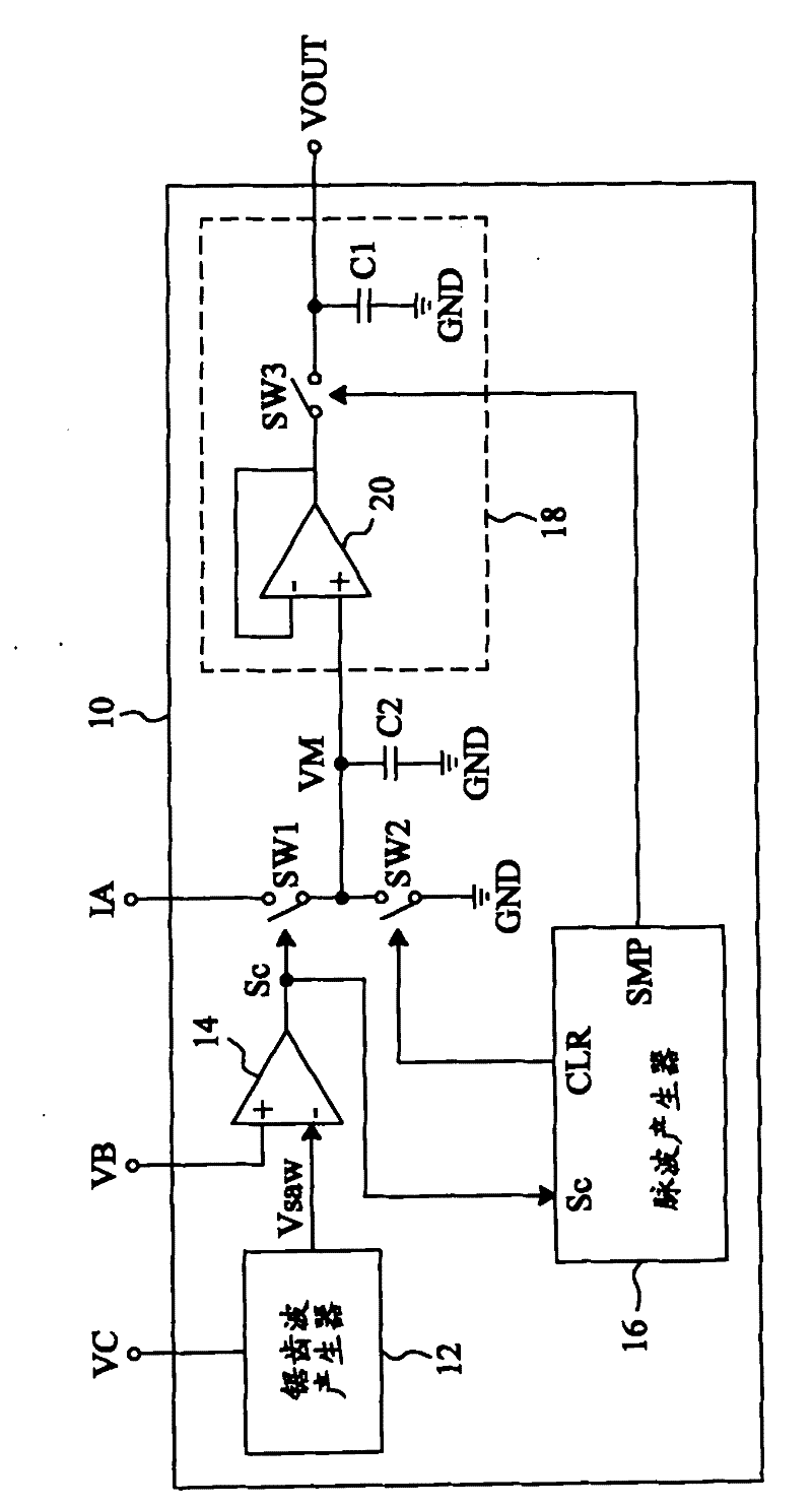
[0014] Such as figure 1 As shown, the multiplier / divider 10 according to the present invention is used to generate an output voltage from an input current IA and input voltages VB and VC

[0015] VOUT=k(IA×VB÷VC), [Formula 1]

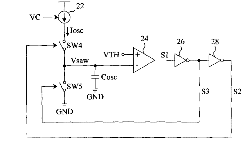
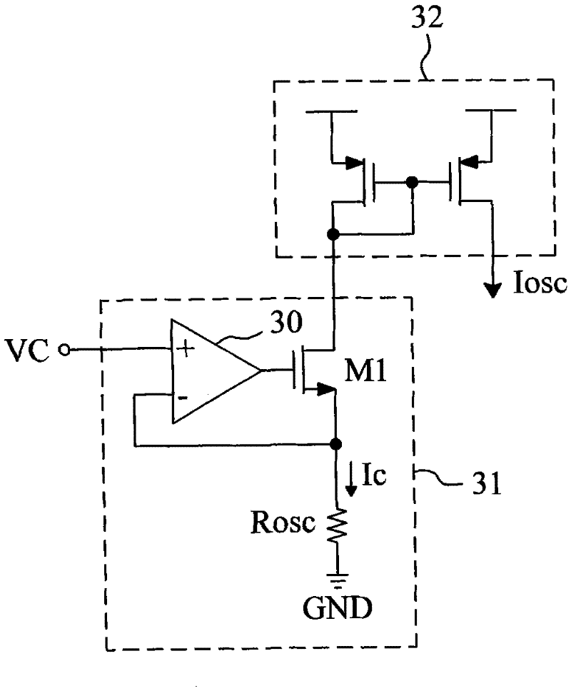
[0016] where k is the scaling factor. In the multiplier and divider 10, the sawtooth wave generator 12 generates a sawtooth wave signal Vsaw according to the input voltage VC, the comparator 14 compares the input voltage VB and the sawtooth wave signal Vsaw to generate a comparison signal Sc, and the pulse wave generator 16 generates a clear signal according to the comparison signal Sc The signal CLR and the sampling signal SMP, the switch SW1 is connected between the input terminal IA and the capacitor C2, and is controlled by the comparison signal Sc, the switch SW2 is connected in parallel with the c...


PUM


Abstract

The invention discloses a multiplier-divider and a method thereof, which are used for multiplying input current by first input voltage and then dividing a product by second input voltage to generate output voltage so as to achieve the advantages of no need of a BJT (Bipolar Junction Transistor), high elasticity and simple circuit. The multiplier-divider comprises a sawtooth wave generator and a comparator, wherein the sawtooth wave generator is used for generating a sawtooth wave signal according to the second input voltage; the comparator is used for comparing the sawtooth wave signal with the first input voltage to generate a comparison signal; and the comparison signal is used for controlling that a capacitor is charged by the input current to generate capacitor voltage with promotional relation with the output voltage. The method comprises the following steps of: generating the sawtooth wave signal of which the period is inversely proportional to the second output voltage according to the second input voltage; comparing the sawtooth wave signal with the first input voltage to generate the comparison signal; charging the first capacitor by the input current according to the comparison signal to generate the capacitor voltage which has promotional relation with the output voltage; and controlling the first capacitor to discharge according to a clear signal.

Description

technical field [0001] The invention relates to a multiplication and division device and its method. Background technique [0002] Traditional multipliers and dividers are composed of bipolar junction transistors (Bipolar Junction Transistor; BJT), so there are many disadvantages caused by BJT. For example, BJT has a high temperature coefficient, so the output of its multiplier and divider is also affected by temperature; BJT has high gain, so the slight distortion of the input signal of its multiplier and divider may cause the output of multiplier and divider Influence, so the anti-noise ability of the multiplier and divider is poor; the linear operation range of BJT is narrow, thus limiting the range of the input signal of the multiplier and divider composed of it. [0003] U.S. Patent No. 6,812,769 proposes a multiplier and divider without using BJT. Although it eliminates the shortcomings caused by BJT, it requires a more complicated circuit, and the cycle of the sawtoo...

Claims


Application Information

Patent Timeline
IPC IPC(8): G06G7/16
Inventor 吴信义黄志丰
Owner RICHPOWER MICROELECTRONICS
Learn More