

Sound energy visualizer
A technology of sound energy and observation instrument, which is applied in the direction of instruments, educational tools, teaching models, etc., can solve the problems that it is difficult to explain the energy of sound waves, the logic is confusing, and the scientific nature is not strong, so as to eliminate the interference of airflow, low cost, and scientific strong effect
Inactive Publication Date: 2011-11-09
雷海平
View PDF0 Cites 1 Cited by
- Summary
- Abstract
- Description
- Claims
- Application Information
AI Technical Summary
Problems solved by technology
[0003] The above experiment has the disadvantages of confusing logic and not strong scientific nature: pointing the open end of the paper tube to the flame, in essence, the airflow during vibration is enhanced, so that the shaking of the flame can be seen. This kind of shaking is difficult to explain that the sound wave has energy.
Method used
View moreImage
Smart ImageViewing Examples

Examples
Embodiment Construction
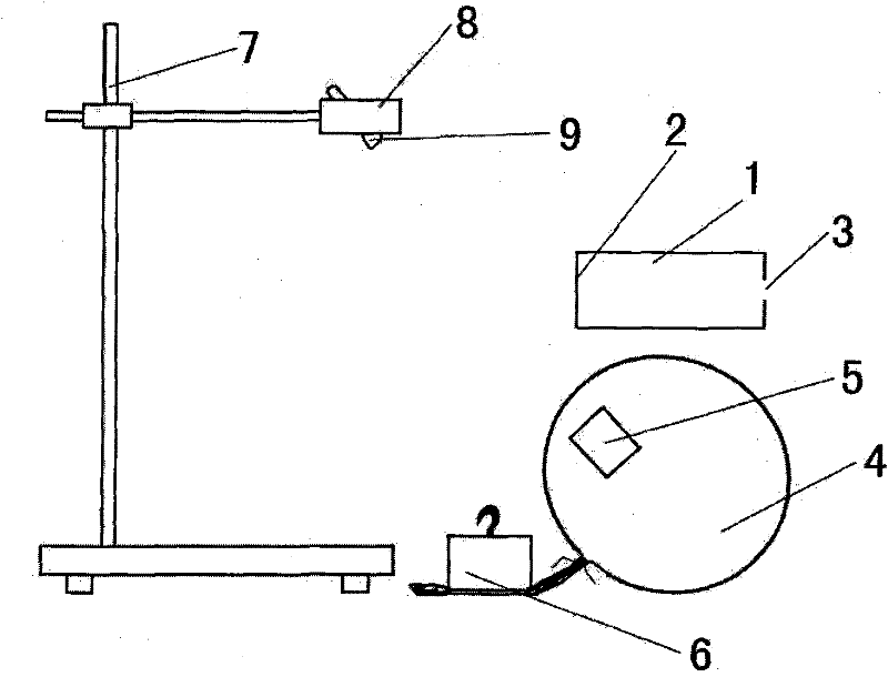
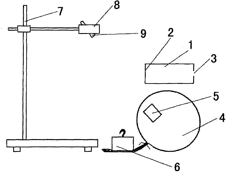
[0010] Such as figure 1 As shown: the sounding body 1 is a paper cylinder with an elastic membrane 2 bound at one end and a hole 3 at the other end. Air bag 4 is light balloon-like object, and air bag 4 is pressed on the desktop with heavy object 6 after being bundled finely, and a small piece of mirror 5 is pasted with double-sided adhesive tape on air bag 4. Laser pointer 9 is fixed by the iron clip 8 of iron frame platform 7.
[0011] The air bag is a balloon, and the support can also be a wooden support.
[0012] The sounding body can also be a loudspeaker connected to an external signal source.
Login to View More PUM
 Abstract
The invention discloses a sound energy visualizer which comprises a sounding body. The sound energy visualizer is characterized by also comprising an air sac, a reflector adhered to the surface of the air sac, a laser pen and a bracket for fixing the laser pen. when the sound energy visualizer is in use, the air sac is put on a desk and the position and height of the bracket are regulated so that laser irradiates the reflector to form a bright light spot on a ceiling; and then the sounding body is knocked or started up so that the light spot continuously sways, which indicates that sound energy is transferred to the air sac actually and shakes the reflector on the air sac. The sound energy visualizer has the beneficial effects that the air sac is extremely light and is easy to sway under the influence of sound wave; the sway of the air sac is amplified by laser reflection so that the reflected light spot continuously and obviously sways on a wall or the ceiling, and the whole spot can be seen; and the back of the sounding body is over against the air sac, the light spot still sways, and the interference of air flow is eliminated; the sound energy visualizer has the advantages of clear logic, high scientificity and low cost and is convenient to operate.
Description
Technical field [0001] The invention relates to a middle school physics teaching instrument, in particular to a sound energy observer. Background technique [0002] In the physics textbook of the eighth grade volume 1 of Educational Science Press, the experimental plan for observing the energy of sound is as follows: cut thick paper into a circle, drill a hole in the middle, stick it firmly to one end of the paper tube, and wrap the paper tube with plastic film the other end, and then fasten it with a rubber band, such as figure 1 As shown in the part of the sounding body in the figure, 1 is the sounding body in the figure, 2 is the elastic membrane, and 3 is the hole. Light a candle in front of the paper tube, pick up the paper tube and align the small hole with the ignited flame, hit the plastic film at the other end of the paper tube to make it sound, and the flame can be seen shaking due to the impact of sound waves. [0003] The above-mentioned experiments have the di...
Claims
Login to View More Application Information
Patent Timeline
 Patent Type & Authority Applications(China)
IPC IPC(8): G09B23/14
Inventor 雷海平
Owner 雷海平