Control circuit and control method of switch power supply, light-emitting device and electronic device

一种控制电路、开关电源的技术,应用在电致发光光源、输出功率的转换装置、电光源等方向,能够解决电子设备用户不愉快等问题,达到降低音响噪声的效果

Active Publication Date: 2011-11-09
ROHM CO LTD
View PDF6 Cites 12 Cited by
  • Summary
  • Abstract
  • Description
  • Claims
  • Application Information

AI Technical Summary

Problems solved by technology

This noise occurs in the audible frequency band, so it is unpleasant for users of electronic equipment

Method used


Image

  • Control circuit and control method of switch power supply, light-emitting device and electronic device
  • Control circuit and control method of switch power supply, light-emitting device and electronic device
  • Control circuit and control method of switch power supply, light-emitting device and electronic device

Examples


Embodiment Construction

[0032] Hereinafter, the present invention will be described based on preferred embodiments with reference to the drawings. The same or equivalent structural elements, members, and processes shown in the respective drawings are given the same reference numerals, and corresponding repeated descriptions are omitted. In addition, the embodiment does not limit the invention but is an illustration, and all the features or combinations thereof described in the embodiment are not essential features or combinations of the invention.

[0033] In this specification, the "state where member A and member B are connected", in addition to the case where member A and member B are physically and directly connected, also includes other members that do not affect the electrical connection state between member A and member B. In the case of indirect connection.

[0034] Similarly, the so-called "the state in which the member C is arranged between the member A and the member B", in addition to the cas...


PUM


Abstract

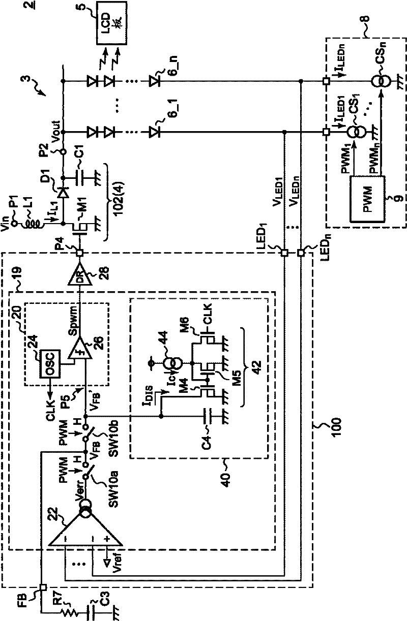
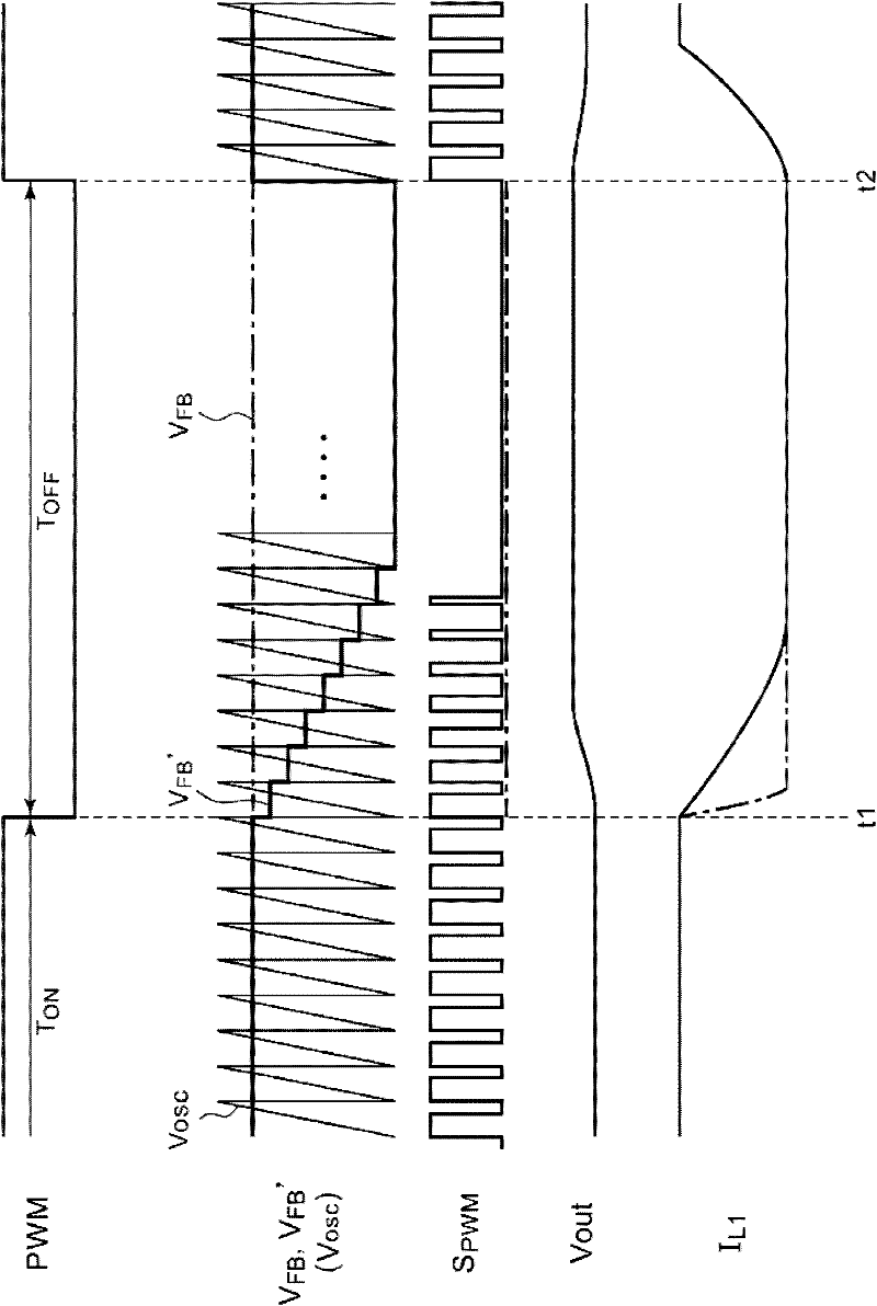
The invention provides a control IC, controlling a switch power supply (4) providing a driving voltage (Vout) for one end of an LED string (6) through intermittence drive. A pulse modulation machine (19) generates a pulse signal (Spwm) whose duty ratio is adjusted during a lightening period, enabling a detection voltage (VLED) of an output voltage (Vout) of the switch power supply (4) to be consistent with a regulated voltage references (Vref). A driver (28) drives a switch transistor (M1) of the switch power supply (4) based on the pulse signal (Spwm). The pulse modulation machine (19) enables the duty ratio of the pulse signal (Spwm) to descend with time during the time from the lightening period to a quenching period. The control IC (100) inhibits the noise of coils at the time of PWM driving.

Description

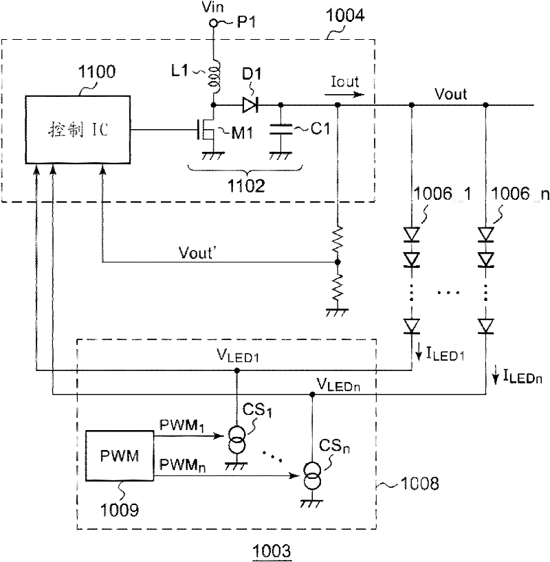
Technical field [0001] The invention relates to a light emitting device. Background technique [0002] In recent years, as backlights or lighting equipment for liquid crystal panels, light-emitting devices using light-emitting elements represented by LEDs (Light Emitting Diodes) have been used. figure 1 It is a circuit diagram showing a configuration example of a light emitting device in the related art. The light emitting device 1003 has a plurality of LED strings 1006_1 to 1006_n, a switching power supply 1004, and a current drive circuit 1008. [0003] Each LED string 1006 includes a plurality of LEDs connected in series. The switching power supply 1004 boosts the input voltage Vin and provides a driving voltage Vout to one end of the LED string 1006_1 to 1006_n. [0004] The current drive circuit 1008 has a current source CS provided for each of the LED strings 1006_1 to 1006_n 1 ~CS n . Each current source CS provides a drive current I corresponding to the target brightness t...

Claims


Application Information

Patent Timeline
Patent Type & Authority Applications(China)
IPC IPC(8): H02M3/156G02F1/13357G09G3/34G09G3/36
CPCH05B33/0827G09G2320/064H05B33/0815G09G2330/028G09G3/3406H02M2001/009Y02B20/346H02M3/156H05B45/3725H05B45/46H02M1/009Y02B20/30
Inventor 内本大介菊池弘基
Owner ROHM CO LTD
Why Eureka
Try Eureka