Plasma method for disposing of waste material, and apparatus therefor

A technology of waste and equipment, applied in the field of waste material treatment, to prevent the formation of harmful substances

Inactive Publication Date: 2011-11-09
RE 2
View PDF1 Cites 4 Cited by
  • Summary
  • Abstract
  • Description
  • Claims
  • Application Information

AI Technical Summary

Problems solved by technology

Even with reference to "holes for valves", the problem of melt hardening inside the valves remains unresolved

Method used


Image

  • Plasma method for disposing of waste material, and apparatus therefor
  • Plasma method for disposing of waste material, and apparatus therefor
  • Plasma method for disposing of waste material, and apparatus therefor

Examples


Embodiment Construction

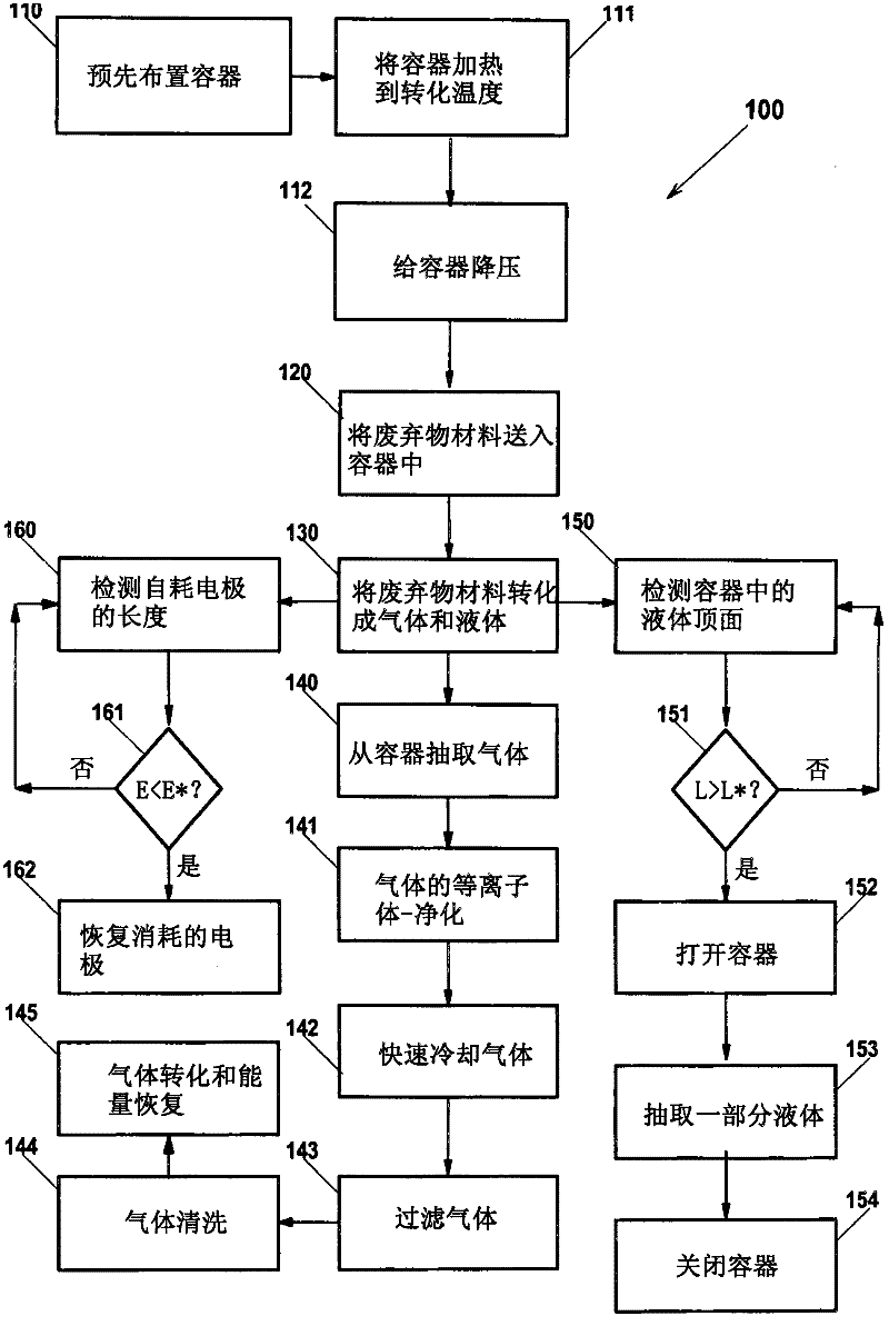
[0090] refer to figure 1 is a flow chart depicting a method 100 for converting waste materials according to the present invention. The method 100 comprises a step 110 of pre-arranging the vessel, a step 111 of heating the vessel to a transition temperature typically set between 1600°C and 2000°C and a step 112 of depressurizing the vessel to an absolute pressure, preferably set at 1 millibar Between to 10 millibars, and most preferably around 4 millibars. The depressurization step 112 is followed by the step 120 of sending the waste material into the container; step 120 is implemented in such a way as to prevent air from entering the container with the waste material, which would cause a loss of vacuum and a portion of the vacuum. Waste material burning. The conversion temperature is high enough to cause and maintain a step 130 in which the waste material is converted into two fractions, an ionized gas 11 (i.e., plasma) and a substantially liquid fraction 9 which accumulates...


PUM


Abstract

Provided are a method and an apparatus based on a reactor vessel (201) that is brought to a predetermined vacuum degree, in particular said vacuum degree set between 2 and 6 absolute millibar, an to a high temperature. A waste material is continuously introduced in the vessel (202), in particular a solid waste material (5) is introduced in such a way that a vacuum loss from the vessel (201) is prevented. Owing to the high temperature, waste material (5) forms a plasma that undergoes a molecular rearrangement, which gives origin to a substantially liquid residue that is collected in a bottom portion (204) of reactor (201), and to a gas (11). The gas (11), which mainly comprises carbon monoxide, hydrogen, carbon dioxide and steam, i.e. a typical syngas composition, is continuously taken away from the vessel (201) through a duct (12), and is sent to subsequent treatments to obtain a gas fuel that can be burnt by devices such as a gas turbine, a motor or a boiler. The high temperature in reactor (201) is maintained due to a current in the form of electric discharges (20) that is established between two electrodes (21,22) below the liquid head (7). The substantially liquid residue is periodically discharged to maintain a liquid head height (7) not exceeding a reference height value H*, in such a way that air inlet into vacuum loss from the vessel (201) is prevented.

Description

technical field [0001] The present invention relates to a method for waste material treatment, which converts waste into plasma. The invention also relates to a device for carrying out the method. [0002] The method and apparatus are well suited for the treatment of solid, liquid or gaseous waste materials which may contain organic and inorganic fractions. In particular, waste material can be municipal waste, hospital or surgical waste, hazardous or infected waste, sewage sludge, metal workshop waste, slaughterhouse waste, farm waste, ground tires, etc. . Background technique [0003] There is a felt need for waste material treatment technologies that overcome the known disadvantages of conventional technologies such as landfills and incineration, and potentially allow energy recovery. [0004] In particular, methods of heating waste materials to a temperature at which their organic fractions are converted into ionized gases (ie, plasmas) are known. Under these conditio...

Claims


Application Information

Patent Timeline
Patent Type & Authority Applications(China)
IPC IPC(8): B09C1/06F23G5/00F23G5/08B09B3/00
CPCF23J1/00F23G2205/121F23G2205/18B09B3/00F23G5/085B09C1/06F23G5/444F23G5/448
Inventor M·法比里E·森诺
Owner RE 2
Why Eureka
Try Eureka