Method of manufacturing lamp and quartz bulb

一种制造方法、真空管的技术,应用在石英真空管领域,能够解决材料费增大等问题,达到降低成本的效果

Inactive Publication Date: 2011-11-09
IWASAKI ELECTRIC CO LTD
View PDF5 Cites 2 Cited by
  • Summary
  • Abstract
  • Description
  • Claims
  • Application Information

AI Technical Summary

Problems solved by technology

[0020] Furthermore, in order to meet the requirements of high efficiency and long life of the lamp, high-precision quartz is used in the quartz vacuum tube, and the raw material price is very high compared with the existing quartz. Since the relationship between both ends is cut off, the quartz vacuum tube must be formed to be sufficiently longer than the actual lamp, and an extremely expensive high-purity quartz tube must be used for the part that is finally cut off. Therefore, there is a problem that the cost of materials increases.

Method used


Image

  • Method of manufacturing lamp and quartz bulb
  • Method of manufacturing lamp and quartz bulb
  • Method of manufacturing lamp and quartz bulb

Examples


Embodiment 1

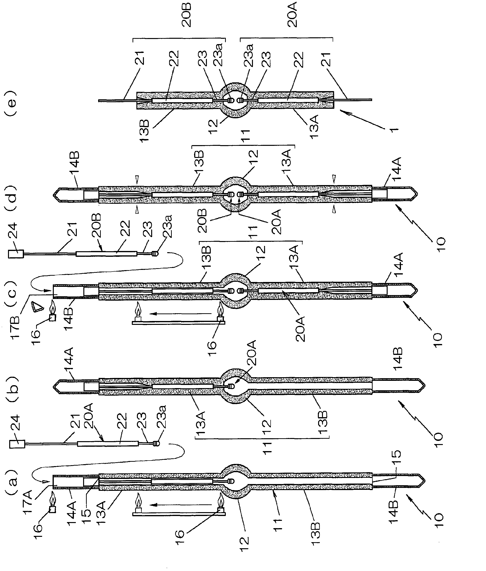
[0062] In this example, a method of manufacturing an ultra-high pressure mercury lamp 1 with a rating of 150W will be described.

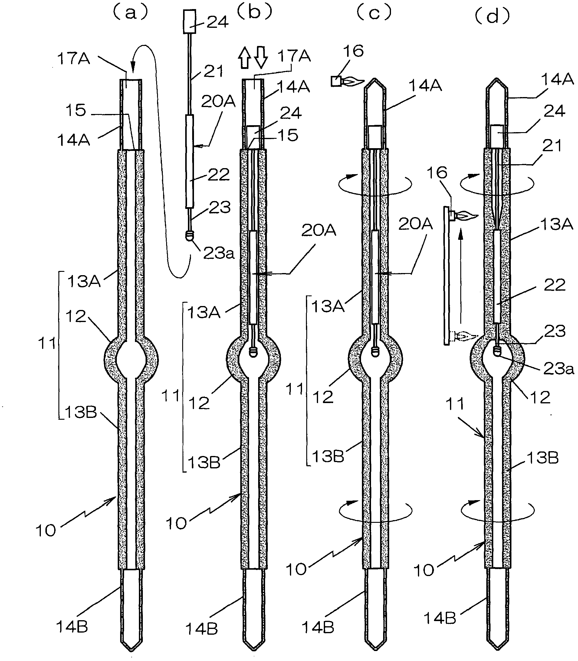
[0063] In this method, the electrode holders 20A and 20B are inserted into the quartz vacuum tube 10 from the openings at both ends of the quartz vacuum tube 10 , and these are packaged in a state where the inside is under a negative pressure.

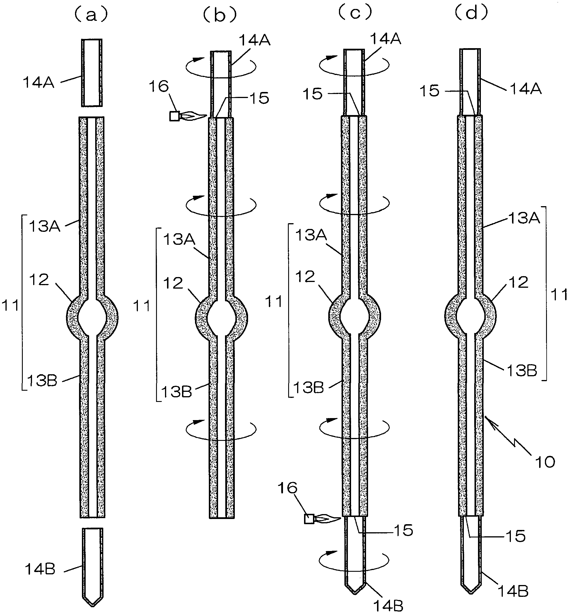
[0064] figure 1 Represents the overall process diagram, including: processing steps from the quartz vacuum tube (refer to figure 2 ) The first electrode holder packaging process ( figure 1 (a)~(b)), the 2nd electrode holder encapsulation process that carries out the 2nd electrode holder 20B encapsulation that is inserted from the other end side of quartz vacuum tube 10 ( figure 1 (c) to (d)), an annealing process for removing deformation generated on the quartz, and a cutting process for cutting both ends of the quartz vacuum tube 10 and processing them into predetermined lengths ( figure 1 (e)), ea...


PUM


Abstract

The purpose of the invention is that an electrode end is accurately positioned so that the arc length is constant, and when electrode mounts are sealed by heating a sealing part, a leakage caused by bending and twisting of a molybdenum foil is prevented from occurring at the sealed part. In order to reach the purpose, a quartz bulb (10) has openings at opposite ends of a body pipe (11) where a light emission part and sealing parts are formed, and the quartz bulb (10) also has a positioning step (15) formed by fusion bonding extension pipes (14A, 14B) to the openings. The extension pipes (14A, 14B) have an internal diameter greater than the internal diameter of the openings. The electrode mounts (20A, 20B) having a positioning engagement part (24) located at a position a predetermined distance away from the electrode end is inserted into the quartz bulb, and sealing parts (13A, 13B) are sealed with the positioning engagement part (24) of the electrode mounts (20A, 20B) engaged with the positioning step (15).

Description

technical field [0001] The invention relates to inserting electrode holders (mouts) from openings at both ends of a quartz vacuum tube in which a cavity as a light-emitting portion is formed in the middle portion of the quartz tube, and straight tube-shaped sealing portions are formed on both ends thereof, A method of manufacturing a lamp in which the above-mentioned sealing portion is encapsulated in a state where the interior is brought into a negative pressure, and a quartz vacuum tube used therein. Background technique [0002] At present, in the high-pressure discharge lamps generally used in automobile headlights and projector backlights, if the wall thickness distribution of the discharge tube is not uniform, there is a possibility of cracking due to high temperature and high pressure operation. , Therefore, a discharge tube with a uniform wall thickness distribution without the remaining part of the exhaust pipe (exhaust part) (tips) in the light emitting part is use...

Claims


Application Information

Patent Timeline
Patent Type & Authority Applications(China)
IPC IPC(8): H01J9/32
CPCH01J61/368H01J9/326
Inventor 大河原亮山本将二
Owner IWASAKI ELECTRIC CO LTD
Why Eureka
Try Eureka