
Device for improving pipe internal-pressure forming limit and method for improving pipe internal-pressure forming limit by utilizing same

A technology of forming limit and pipe material, which is applied in the field of devices for improving the forming limit of pipe internal pressure, which can solve the problems of poor deformation uniformity, low room temperature forming limit, cracking, etc. little effect

Inactive Publication Date: 2011-11-16
HARBIN INST OF TECH
View PDF4 Cites 9 Cited by
  • Summary
  • Abstract
  • Description
  • Claims
  • Application Information

AI Technical Summary

Problems solved by technology

[0005] The purpose of the present invention is to solve the problems of poor deformation uniformity, cracking caused by local excessive thinning, and low room temperature forming limit in the existing pipe internal pressure forming process. The present invention provides a method for increasing the pipe internal pressure forming limit. Device and method for improving pipe internal pressure forming limit by using it

Method used


Image

  • Device for improving pipe internal-pressure forming limit and method for improving pipe internal-pressure forming limit by utilizing same
  • Device for improving pipe internal-pressure forming limit and method for improving pipe internal-pressure forming limit by utilizing same
  • Device for improving pipe internal-pressure forming limit and method for improving pipe internal-pressure forming limit by utilizing same

Examples


specific Embodiment approach 1

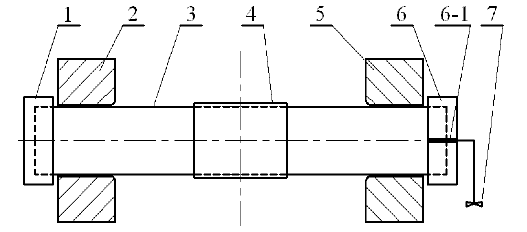
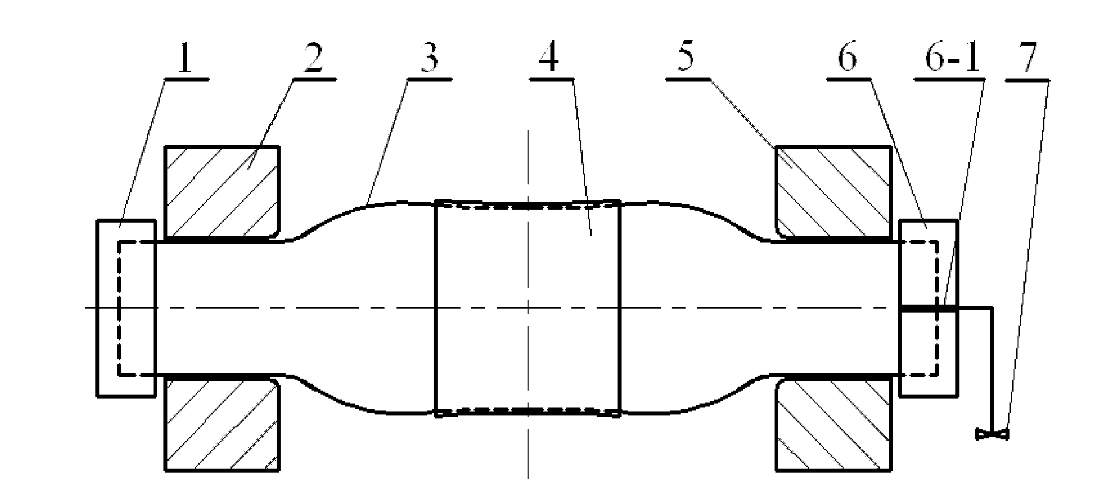
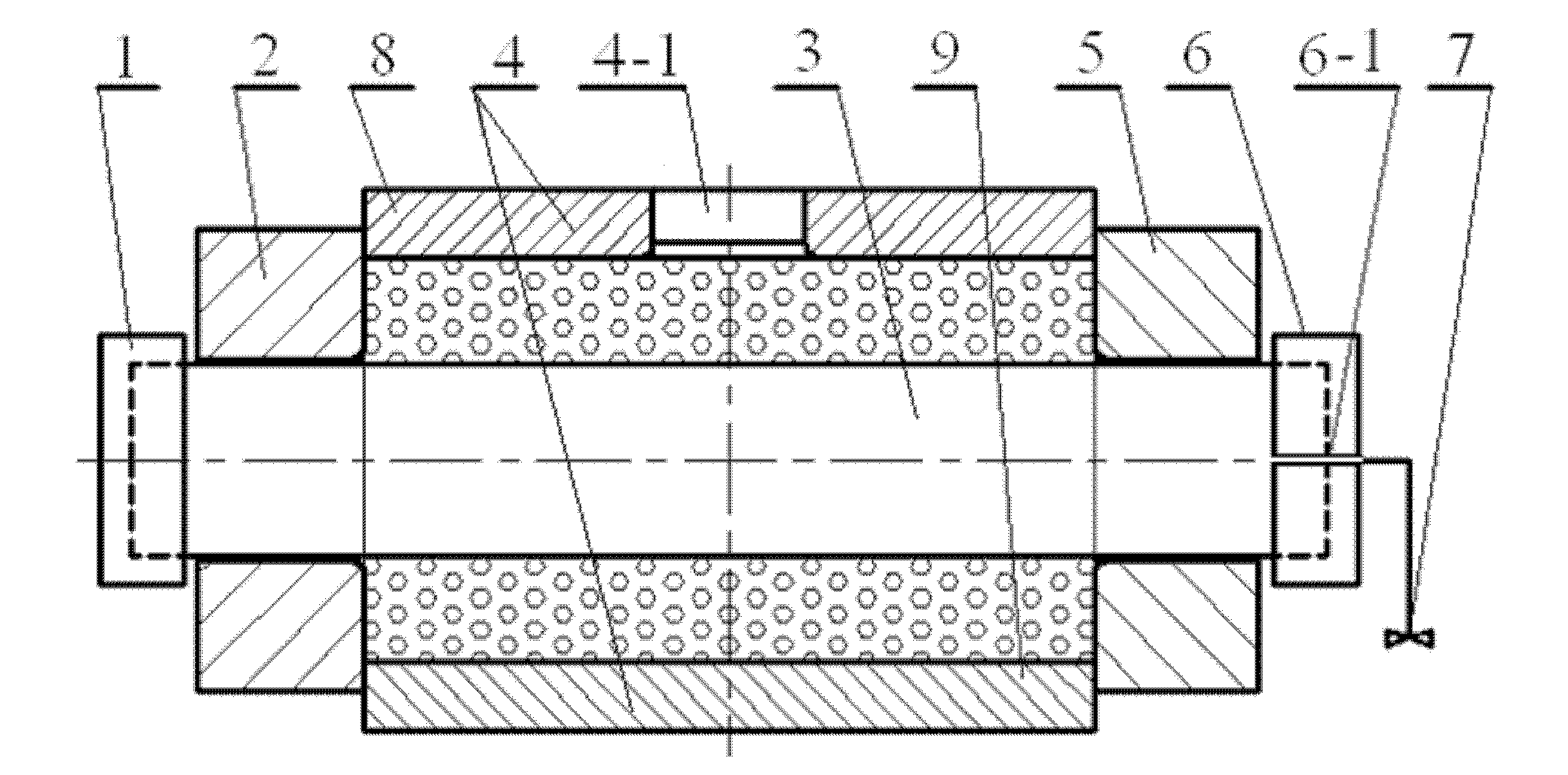
[0018] Specific implementation mode one: combine figure 1 , to illustrate the first device for increasing the limit of internal pressure forming of pipes in this embodiment. The device for increasing the limit of internal pressure forming of pipes includes a first sealing device 1, a first mold frame 2, a second mold frame 5, a first Two sealing devices 6 and pressure regulating valves 7, the first formwork 2 and the second formwork 5 fix the pipe material 3, the first sealing device 1 seals one end of the pipe material 3, and the second sealing device 6 seals the other end of the pipe material 3 A passage 6-1 is provided on the axis of the second sealing device 6, and the output end of the pressure regulating valve 7 is connected to the passage 6-1 on the second sealing device 6 through a pipeline, and the passage 6-1 connects the pipe 3 The inner cavity communicates with the output end of the pressure regulating valve 7, wherein a restraint sleeve 4 is provided in the middle...

specific Embodiment approach 2

[0020] Embodiment 2: This embodiment differs from Embodiment 1 in that the length of the restraining sleeve 4 is preferably 1 / 4 to 1 / 3 of the pre-formed length of the pipe 3 . Other components and connections are the same as those in the first embodiment.

specific Embodiment approach 3

[0021] Embodiment 3: This embodiment differs from Embodiment 1 or Embodiment 2 in that the inner diameter of the constraint sleeve 4 is 0.6 mm to 0.9 mm larger than the outer diameter of the pipe 3 . Other compositions and connections are the same as those in Embodiment 1 or 2.


PUM

PropertyMeasurementUnit
particle diameteraaaaaaaaaa

Abstract

The invention provides a device for improving pipe internal-pressure forming limit and a method for improving pipe internal-pressure forming limit by utilizing the same, which relate to a device and method for improving pipe internal-pressure forming limit and solve the problems of poor deformation uniformity, cracking due to the excessive thinning of a local part and low room-temperature forminglimit in the traditional pipe internal-pressure forming process. In the device provided by the invention, a constraint sleeve is arranged at the middle part of the outer side wall of a pipe or a die is arranged outside the pipe; in the method provided by the invention, the constraint sleeve is arranged at the middle part of the outer side wall of the pipe or the die is arranged outside the pipe, a filler is added into the gap between the die and the pipe, the pipe is fixed on a die frame with the two ends sealed, an internal pressure is introduced into the inner cavity of the pipe, and forming is finally carried out. In the invention, a back pressure is applied to the outer side of the pipe, so that the stress state of the pipe at a sectional part subjected to the maximum deformation is changed into a two-pulling and one-pressing mode from a two-pulling mode, thereby avoiding the possibility that a cracking defect is caused as the wall thickness of the part is excessively thinned, improving the room-temperature forming limit, and increasing the expansion ratio to 30-45%.

Description

technical field [0001] The invention relates to a device and method for increasing the limit of internal pressure forming of pipes. Background technique [0002] Lightweight materials and structures have become the main trend and development direction in aerospace, automobile manufacturing and other fields. At the same time, it is also one of the effective ways to achieve energy saving and emission reduction. While lightweight metal materials such as aluminum alloys, magnesium alloys, and high-strength steels are widely used, hollow variable-section members have become the ideal structural form of choice. Lightweight structure is mainly based on ensuring the strength, through reasonable design of variable cross-section, optimization of shape components, etc., so as to fully and effectively play the functions of components. However, this kind of optimization often leads to the complexity of the structure, and it is difficult to form it at one time by traditional stamping and...

Claims


Application Information

Patent Timeline
Patent Type & Authority Applications(China)
IPC IPC(8): B21D26/033B21D26/047B21D26/045
Inventor 林俊峰李峰刘钢
Owner HARBIN INST OF TECH
Learn More