Device and method for moulding and forming micro-turbine

A technology of micro-turbine and compression molding, which is applied in the direction of forming tools, metal processing equipment, manufacturing tools, etc., can solve the problems of unsuitable mass production, low material utilization rate, high processing cost, etc., and achieve good comprehensive mechanical properties and material utilization rate High, high processing efficiency effect

Active Publication Date: 2011-11-16
HARBIN INST OF TECH
View PDF6 Cites 5 Cited by
  • Summary
  • Abstract
  • Description
  • Claims
  • Application Information

AI Technical Summary

Problems solved by technology

[0004] The purpose of the present invention is to provide a micro-turbine forming device and method to solve the problems of low material utilization rate, low processing efficiency, high processing cost and unfavorable mass production when manufacturing micro-turbine in the prior art

Method used


Image

  • Device and method for moulding and forming micro-turbine
  • Device and method for moulding and forming micro-turbine
  • Device and method for moulding and forming micro-turbine

Examples


specific Embodiment approach 1

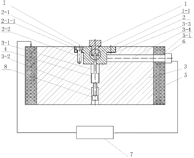
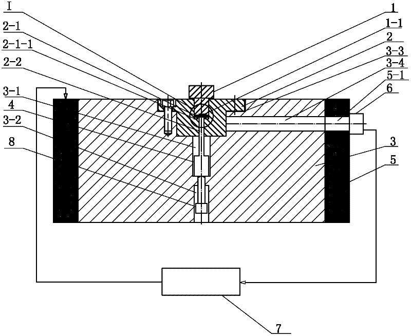
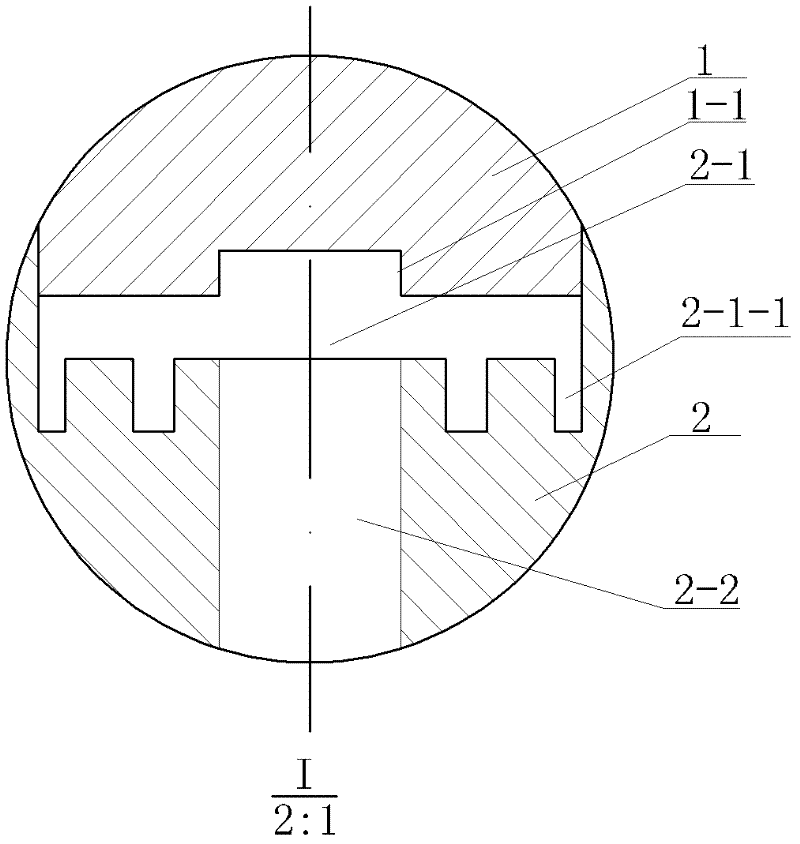
[0015] Specific implementation mode one: combine figure 1 and image 3 Describe this embodiment, the micro-turbine molding device of this embodiment includes a punch 1, a die 2, a die base 3, a push rod 4, an electric heating element 5, a temperature sensor 6, a temperature controller 7 and a first screw 8 The middle part of the upper end surface of the die base 3 is provided with a first groove 3-3, the die 2 is placed in the first groove 3-3 of the die base 3, and the die 2 and the die base 3 are detachably connected The middle part of the lower end surface of the die base 3 is provided with a third hole 3-2, and the die base 3 is provided with a second hole communicating with the two between the first groove 3-3 and the third hole 3-2. Hole 3-1, a fourth hole 3-4 communicated with the first groove 3-3 is provided radially on the side wall of the die holder 3, and a forming groove 2-1 is provided in the middle of the upper end surface of the die 2 , the middle part of the ...

specific Embodiment approach 2

[0017] Specific implementation mode two: combination figure 1 The present embodiment will be described. The materials of the punch 1 , the die 2 , the die holder 3 and the ejector pin 4 of the present embodiment are all 5CrNiMo. With such settings, the material performance is reliable and meets the design requirements. Others are the same as in the first embodiment.

specific Embodiment approach 3

[0018] Specific implementation mode three: combination figure 1 Describe this embodiment, the die 2 and the die base 3 of this embodiment are detachably connected by at least four second screws. In this way, the die is fixed on the die base with the second screw, which is convenient for installation and disassembly, and the die will not be removed from the die base due to the friction between the part and the inner wall of the die during the ejection process after the molded part is formed. Out, and has a uniform force, not easy to cause damage or deformation of parts. Others are the same as in the first embodiment.


PUM

PropertyMeasurementUnit
heightaaaaaaaaaa

Abstract

The invention discloses a device and method for moulding and forming a micro-turbine, and relates to a device and method for forming a micro-turbine, for solving the problems in the prior art having low material utilization rate, low processing efficiency, high processing cost and unsuitable batch production in the event of manufacturing the micro-turbine. The device comprises a male mould, a female mould, a female mould holder, an ejector rod, an electrically heated component, a temperature sensor, a temperature control meter and a first screw. A groove is arranged in the middle of the upperhead face of the female mould holder. The female mould is in the groove of the female mould holder. The female mould and the female mould holder are detachably connected. A formed groove is arranged in the middle of the upper head face of the female mould. A blade groove is arranged on the lower head face of the formed groove. The male mould is in the formed groove of the female mould. The femalemould holder is in the electrically heated component. The electrically heated component and the female mould holder are glidingly connected. A probe of the temperature sensor is contacted with the female mould. A signal output end of the temperature sensor is connected with a signal input end of the temperature control meter. A signal output end of the temperature control meter is connected with the electrically heated component. The device is used for forming the micro-turbine.

Description

technical field [0001] The invention relates to a micro-turbine shaping device and method. Background technique [0002] With the characteristics of small size, light weight, small inertia, low energy consumption and high integration, micro-machines have broad application prospects driven by micro-electro-mechanical systems and micro-system technologies. The micro impeller pump is a micro fluid machine with fluid as the medium, and has broad application prospects in medical treatment, aerospace and modern industry. The principle of the micro impeller pump is to continuously transport liquid through the rotation of the micro impeller, which has the advantages of high efficiency, stable performance and long life. Its key component is the micro impeller, which has an important impact on the efficiency, life and stability of the pump. Therefore, it is of great significance to process high-quality, low-cost micro-impeller parts. At present, the micro-turbine mainly adopts MEMS...

Claims


Application Information

Patent Timeline
Patent Type & Authority Applications(China)
IPC IPC(8): B21D53/26B21D22/02B21D37/10B21D37/16
Inventor 王春举郭斌王传杰单德彬迟关心徐杰王玉魁王振龙
Owner HARBIN INST OF TECH
Why Eureka
Try Eureka