Scanning probe microscope body with isolated imaging scanning and rough approximation
An imaging scanning and scanning probe technology, applied in the field of scanning probe microscopy, can solve the problems of unstable and unstable relative position between the probe and the sample, and achieve the effects of improving accuracy and resolution, reducing noise and reducing costs.
- Summary
- Abstract
- Description
- Claims
- Application Information
AI Technical Summary
Problems solved by technology
Method used
Image

Examples
Embodiment 1
[0024] Example 1: Rough Approximation Imaging Scanning and Rough Approximation Isolated Scanning Probe Microscope Mirror Body under Gravity
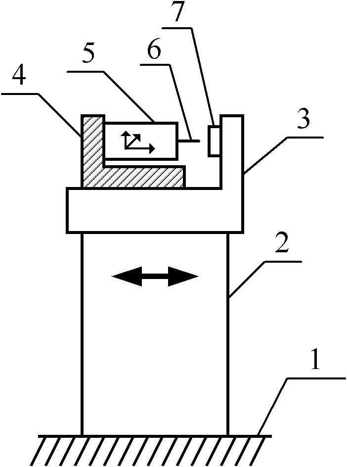
[0025] See attached figure 1 In this embodiment, rough approximation imaging scanning under gravity and a scanning probe microscope mirror body isolated from coarse approximation include XYZ piezoelectric positioner 5, X piezoelectric positioner 2, XYZ piezoelectric positioner frame 4, and X piezoelectric positioner Holder 1, sample rack 3, X piezoelectric positioner 2 is fixed between sample rack 3 and X piezoelectric positioner seat 1, XYZ piezoelectric positioner 5 is fixed on XYZ piezoelectric positioner frame 4, X piezoelectric positioner The positioning direction of the positioner 2 is perpendicular to the direction of gravity, and the XYZ piezoelectric positioner frame 4 is pressed on the sample holder 3 by gravity and is free in the positioning direction of the X piezoelectric positioner 2 .
[0026] The working principle of thi...
Embodiment 2
[0027] Example 2: Tangential Piezoelectric Stack-Driven Imaging Scanning and Coarse Approximation Isolated Scanning Probe Microscope Mirror Body
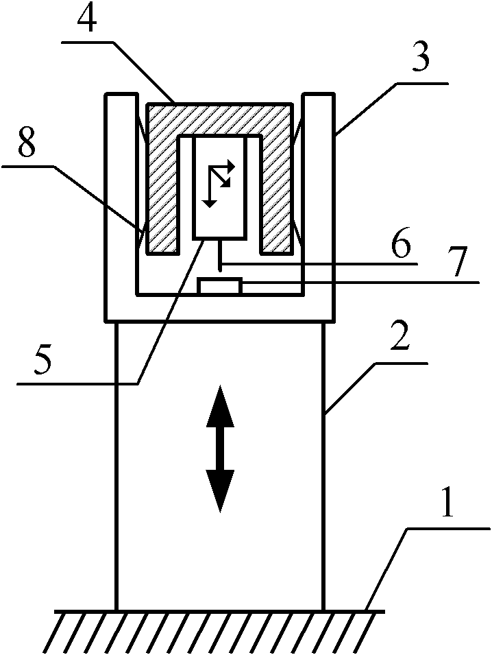
[0028] In the above-mentioned embodiment 1, the X piezoelectric positioner 2 may be a tangential piezoelectric stack (shear piezo stack), so that the tangential piezoelectric stack is vertically stacked with its tangential piezoelectric sheets (shear piezo plates) When fixed on the X piezoelectric locator seat 1, the positioning direction of its top is horizontal, that is, perpendicular to the direction of gravity, so that the XYZ piezoelectric locator frame 4 together with the XYZ piezoelectric locator fixed on it can be driven in the horizontal direction. The positioner 5 is thrown towards the sample 7 fixed on the sample holder 3 step by step in an inertial step, so as to realize a rough approach. The purpose of using a tangential piezoelectric stack here is to increase thrust and reduce drive low voltage.
Embodiment 3
[0029] Example 3: Scanning Probe Microscope Mirror Body with Guided Imaging Scanning and Coarse Approximation Isolation
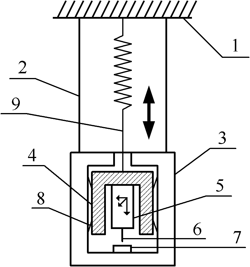
[0030] In the above-mentioned embodiments 1 and 2, a guide rail along the positioning direction of the X piezoelectric positioner 2 is provided between the XYZ piezoelectric positioner frame 4 and the sample frame 3 . Its purpose is to make the X piezoelectric positioner 2 slide on the guide rail when driving the XYZ piezoelectric positioner frame 4 to inertially step on the sample holder 3. On the one hand, the friction coefficient between the sliding surfaces can be improved. Small is more stable, slip is easier and more reliable, and on the other hand makes inertia stepping (coarse approximation) a more directional move.
PUM
 Abstract
Description
Claims
Application Information