Cable connector

A cable connector and cable technology, applied in the direction of connection, conductive connection, two-part connection device, etc., can solve the problems of cable connector enlargement, data transmission rate limitation, and increase of cable connector manufacturing cost, etc. Achieve the effect of reducing size, increasing signal transmission rate, and facilitating manufacturing

Inactive Publication Date: 2011-11-16
FOXCONN (KUNSHAN) COMPUTER CONNECTOR CO LTD +1
View PDF4 Cites 4 Cited by
  • Summary
  • Abstract
  • Description
  • Claims
  • Application Information

AI Technical Summary

Problems solved by technology

[0002] Cable connectors are important components for transmitting signals between electronic devices. After years of development, the types of cable connectors have become increasingly rich, forming a variety of transmission protocols that meet USB, SATA, HDMI, SAS, Displayport, etc. Cable connectors. Most of the above-mentioned different cable connectors transmit signals through the metal conductors in the cables and the metal terminals in the connectors. However, using this method for data transmission will encounter some problems: First, The data transmission rate is limited, which cannot satisfy large-capacity and high-speed data transmission; secondly, as the data transmission rate increases, the requirements for the structure and electrical performance of the cable connector also increase, increasing the manufacturing cost of the cable connector ; Again, in order to increase the transmission rate of the cable connector, the number / size of metal terminals and cables also tends to increase / increase, which causes the cable connector to become larger, which does not meet the requirements of the miniaturization of electronic products. trend

Method used


Image

  • Cable connector
  • Cable connector
  • Cable connector

Examples


Embodiment Construction

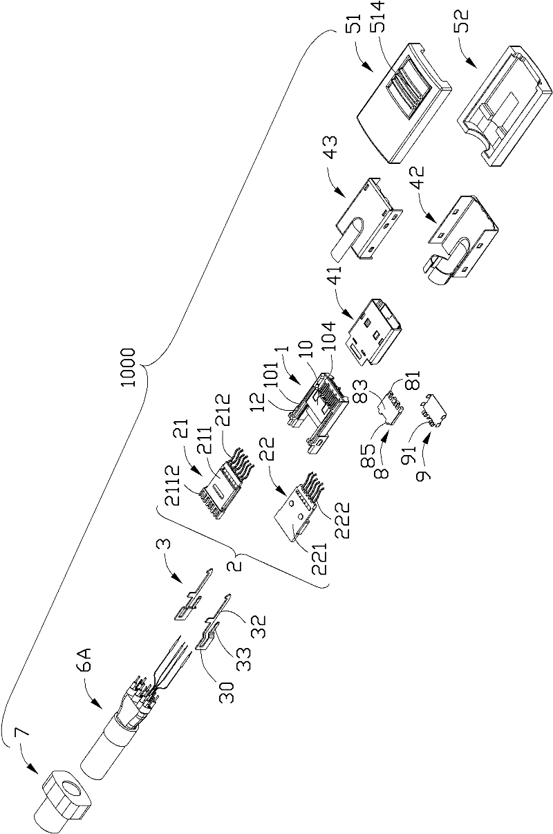
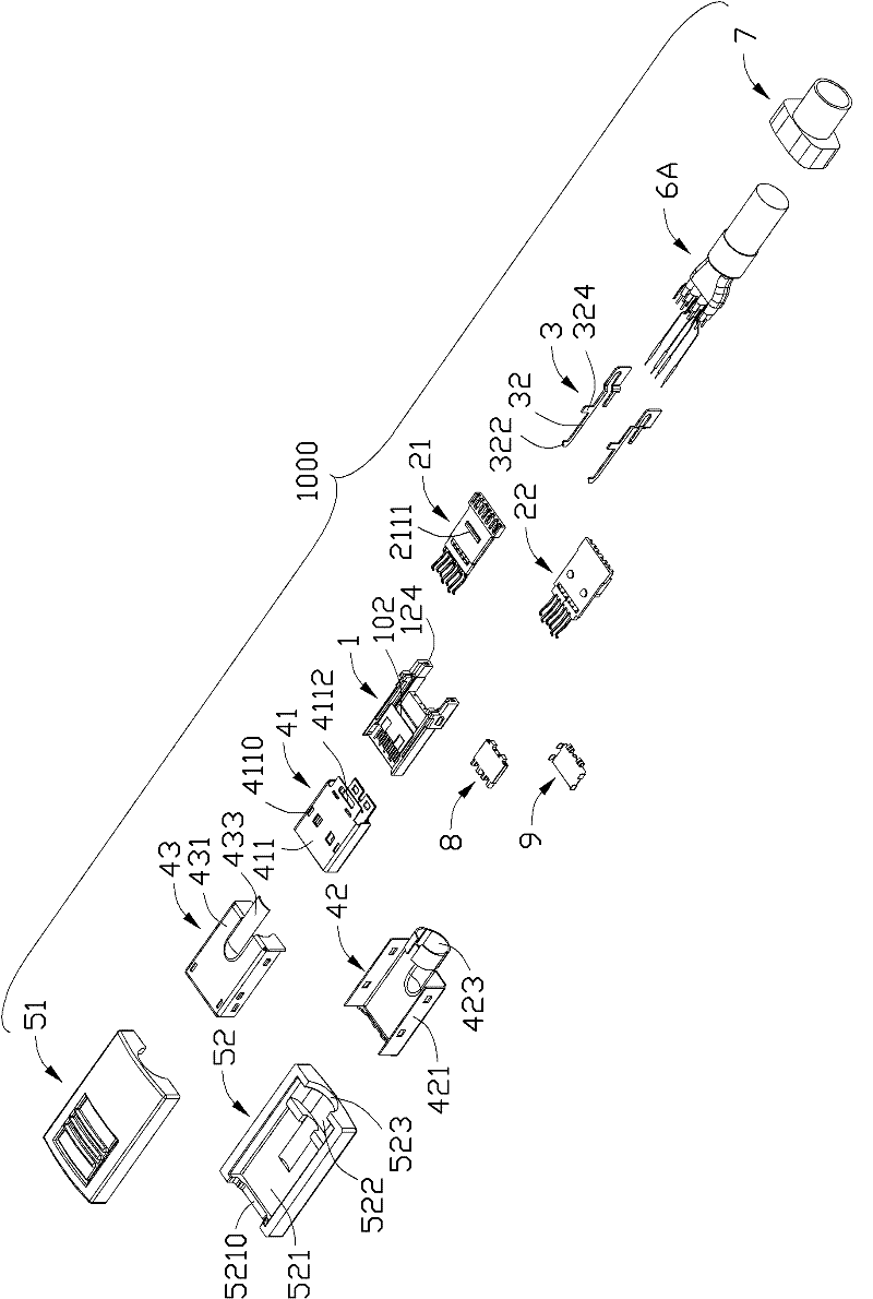
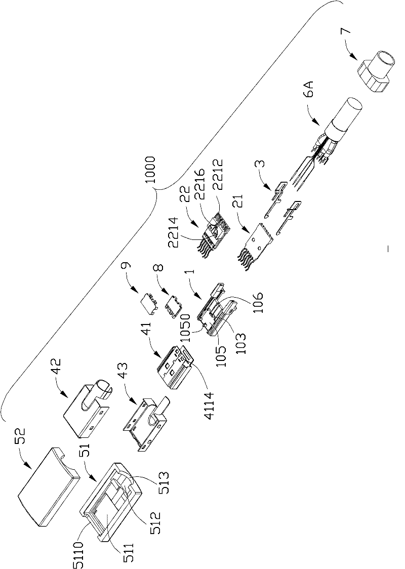
[0019] see Figure 1 to Figure 8 , the cable connector 1000 of the first embodiment of the present invention includes an insulating body 1, a terminal module 2, a pair of buckle elements 3, a metal shell, an insulating shell, a cable 6A, and a stress relief member 7 formed at the front end of the cable 6 , an optical module 8 and an optical module fixing cover 9 .

[0020] The insulating housing 1 includes a main body 10 and a pair of mounting arms 12 extending rearward from two sides of a rear edge of the main body 10 . A pair of receiving grooves 101 are recessed downwards from both sides of the upper surface of the main body 10 and the front of the mounting arm 12 respectively. A receiving cavity 102 is formed by indenting forward from the middle of the rear edge of the main body 10 . A front portion of the upper surface of the main body 10 is provided with a recessed portion 104 , and the recessed portion 104 communicates with the receiving cavity 102 . A groove 105 is ...


PUM


Abstract

The invention discloses a cable connector, comprising an insulating body, a conducting terminal, an optical module and a cable, wherein the conducting terminal comprises a plurality of signal terminal pairs; the cable comprises a plurality of twisted-pair components, an optical fiber component and insulation sheaths which are cladded outside the twisted-pair components and the optical fiber component; the twisted-pair components are arranged at two sides of the optical fiber component symmetrically and connected with the signal terminal pairs; and the optical fiber component is connected with the optical module.

Description

【Technical field】 [0001] The invention relates to a cable connector, in particular to a cable connector which can be used to transmit photoelectric signals. 【Background technique】 [0002] Cable connectors are important components for transmitting signals between electronic devices. After years of development, the types of cable connectors have become increasingly rich, forming a variety of transmission protocols that meet USB, SATA, HDMI, SAS, Displayport, etc. Cable connectors. Most of the above-mentioned different cable connectors transmit signals through the metal conductors in the cables and the metal terminals in the connectors. However, using this method for data transmission will encounter some problems: First, The data transmission rate is limited, which cannot satisfy large-capacity and high-speed data transmission; secondly, as the data transmission rate increases, the requirements for the structure and electrical performance of the cable connector also increase, ...

Claims


Application Information

Patent Timeline
Patent Type & Authority Applications(China)
IPC IPC(8): H01R13/02H01R13/514
CPCH01R24/62G02B6/3817H01R9/035H01R13/65915
Inventor 吴荣发
Owner FOXCONN (KUNSHAN) COMPUTER CONNECTOR CO LTD
Why Eureka
Try Eureka