Vacuum processing apparatus and vacuum transfer apparatus

一种真空处理装置、运送装置的技术,应用在输送机物件、运输和包装、炉等方向,能够解决生产率下降、运送效率或生产率下降、运送机器人应对困难等问题

Inactive Publication Date: 2011-11-16
TOKYO ELECTRON LTD
View PDF8 Cites 7 Cited by
  • Summary
  • Abstract
  • Description
  • Claims
  • Application Information

AI Technical Summary

Problems solved by technology

[0008] However, although the above-mentioned itinerant pick-and-place method can easily perform the transporting action of the transporting robot when the processing time of each processing module is sufficiently longer than the transporting time, it can easily perform the transporting action of the transporting robot, but when the processing time is short, the handling of the transporting robot will be difficult. Difficult delivery or reduced productivity
On the other hand, if the post-processing (such as decontamination, cleaning, etc.) performed by the corresponding processing chamber immediately after carrying out (picking up) the processed object takes a long time, the delivery robot is in order to handle the unprocessed object The processed object is placed in front of the processing module until the subsequent processing is completed. Due to the long waiting time, the overall productivity of the system is greatly reduced.
[0009] In addition, as mentioned above, the number of processing modules (processing chambers) installed tends to increase, and all the substrate transfer operations in the platform are handled by a single vacuum transfer robot, which will soon reach the limit

Method used


Image

  • Vacuum processing apparatus and vacuum transfer apparatus
  • Vacuum processing apparatus and vacuum transfer apparatus
  • Vacuum processing apparatus and vacuum transfer apparatus

Examples


Embodiment Construction

[0066] Hereinafter, preferred embodiments of the present invention will be described with reference to the drawings.

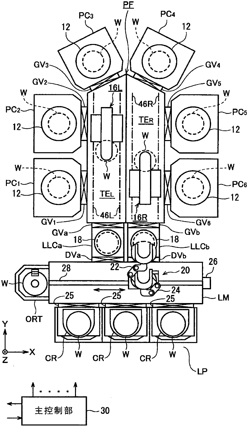
[0067] figure 1 The overall structure of the vacuum processing apparatus of the cluster type frame type according to an embodiment of the present invention is shown. The vacuum processing device is installed in the clean room, and 6 vacuum processing chambers (vacuum processing chambers) PC are arranged in a cluster so as to be adjacent to the periphery of the vacuum platform (vacuum transfer chamber) PF. 1 , PC 2 , PC 3 , PC 4 , PC 5 , PC 6 And 2 loading fixed chambers (loading fixed chamber) LLC a , LLC b The platform has a pentagonal shape in which a pair of sides extending in the depth direction of the device (the Y direction in the figure) is approximately twice longer than the other sides.

[0068] In more detail, the gate valve GV is passed through the gate valve GV on the long side of the left side on the platform PF in the order of clockwise rotation in the...


PUM


Abstract

Transfer performance in a cluster tool is improved without expanding the space at the bottom of the platform in the perpendicular direction. Within a platform (PF), a first transfer robot (16L) has: a transfer body (48L) which can slidably move on a left side guide rail (46L); a transfer base (50L) which can slidably move in the offset direction (X direction); and a slider-type transfer arm (52L) which can turn within a horizontal plane, which can move straight in a direction parallel to the radius of the turn, and which can support one semiconductor wafer (W). A second transfer robot (16R) also has the same configuration and functions as the first transfer robot (16L), however, the transferring or moving directions of the respective sections are bilateral symmetrical to those of the first transfer robot (16L).

Description

Technical field [0001] The present invention relates to a cluster tool type vacuum processing device and a vacuum transport device. Background technique [0002] As a method of a vacuum processing apparatus having a vacuum transfer chamber, a cluster type frame method is known. The cluster structure is a method in which a plurality of processing chambers that perform predetermined processing under negative pressure are arranged around a vacuum platform in order to achieve processing stabilization, continuity, or compounding. It is also called multi-cavity The chamber method is generally adopted in semiconductor manufacturing equipment (for example, refer to Patent Document 1). [0003] Generally speaking, in a cluster-type structure, a processed object is sequentially transported to move it through multiple processing chambers, so that the processed object continuously receives the same type or different types of vacuum processing. In the manufacture of semiconductor devices, CVD...

Claims


Application Information

Patent Timeline
Patent Type & Authority Applications(China)
IPC IPC(8): H01L21/677B65G49/07
CPCH01L21/67742H01L21/67196B25J5/02B25J11/0095H01L21/6719H01L21/67201H01L21/6838H01L21/68707
Inventor 广木勤
Owner TOKYO ELECTRON LTD
Why Eureka
Try Eureka