Cable connector and antenna component
A technology for cable connectors and antenna elements, which is applied in the directions of antenna connectors, connections, antennas, etc., can solve the problems of high manufacturing cost, high assembly requirements, and difficult thickness, and achieve reduced manufacturing costs, simplified assembly processes, and excellent performance. easy effect
- Summary
- Abstract
- Description
- Claims
- Application Information
AI Technical Summary
Problems solved by technology
Method used
Image
Examples
no. 1 approach
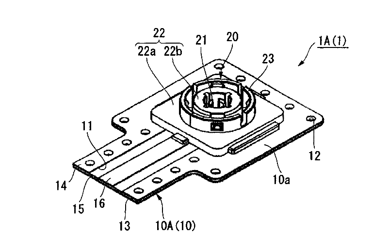
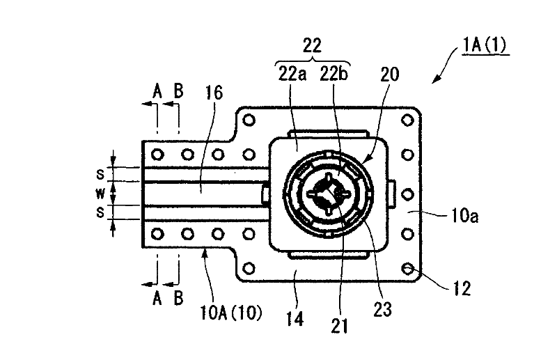
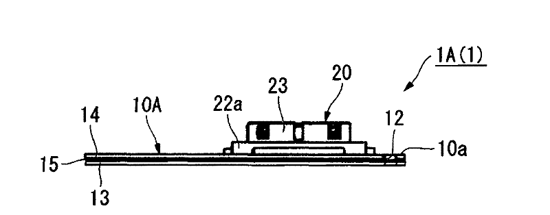
[0056] Figure 1A ~ Figure 1E It is a schematic diagram showing the first embodiment of the cable connector of the present invention. Figure 1A It is a perspective view of this embodiment. Figure 1B It is a plan view of this embodiment. Figure 1C It is a side view of this embodiment. Figure 1D is along Figure 1B A cross-sectional view of line A-A. Figure 1E is along Figure 1B A cross-sectional view of the B-B line.
[0057] The cable connector 1A ( 1 ) of the present embodiment is schematically constituted by a wiring board 10A ( 10 ) and a plug connector 20 .
[0058] Wiring board 10A has first conductor 13 , insulating material 15 , and second conductor 14 , and these are sequentially stacked at substantially equal intervals. As the insulating material 15, for example, polyimide resin, polyethylene naphthalate resin, aramid resin, liquid crystal polymer (LCP) or the like is used.
[0059] A part of the second conductor 14 is cut away to form a slit 11, and the...
no. 2 approach
[0084] Figure 4 It is a schematic perspective view which shows 2nd Embodiment of the cable connector of this invention.
[0085] exist Figure 4 in, for with Figure 1A ~ Figure 2B Components that are the same as those of the first embodiment shown are denoted by the same reference numerals, and description thereof will be omitted.
[0086] The difference between the cable connector 1B(1) of the present embodiment and the cable connector 1A(1) of the above-mentioned first embodiment is that on one surface of the first conductor 13 (the other surface 10b of the wiring board 10A) The plug connector 20 is provided on the top and the coaxial cable 41 electrically connected to the signal transmission path 16 is provided on one surface of the first conductor 13 at one end of the wiring board 10A.
[0087] The coaxial cable 41 passes through a central conductor 42 made of a single-core wire, a stranded wire, or the like, an insulator 43 covering its outer periphery, an outer conduc...
no. 3 approach
[0093] Figure 5A ~ Figure 5D It is a schematic diagram showing the third embodiment of the cable connector of the present invention. Figure 5A It is a perspective view of this embodiment. Figure 5B It is a plan view of this embodiment. Figure 5C is along Figure 5B A cross-sectional view of line A-A. Figure 5D is along Figure 5B A cross-sectional view of the B-B line.
[0094] exist Figure 5A ~ Figure 5D Herein, the same reference numerals are attached to the same constituent elements as those of the above-mentioned first embodiment, and description thereof will be omitted.
[0095] The cable connector 1C(1) of this embodiment differs from the cable connector 1A(1) of the first embodiment above in that the wiring board 10B(10) sequentially connects the first conductor 13, the second The conductor 14 and the third conductor 17 are laminated with the insulating material 15 interposed therebetween. These first conductors 13 , second conductors 14 , and third conduc...
PUM
 Abstract
Description
Claims
Application Information
 - R&D
- Intellectual Property
- Life Sciences
- Materials
- Tech Scout
- Unparalleled Data Quality
- Higher Quality Content
- 60% Fewer Hallucinations
Browse by: Latest US Patents, China's latest patents, Technical Efficacy Thesaurus, Application Domain, Technology Topic, Popular Technical Reports.
© 2025 PatSnap. All rights reserved.Legal|Privacy policy|Modern Slavery Act Transparency Statement|Sitemap|About US| Contact US: help@patsnap.com


